A flue gas waste heat deep recovery system

A technology for recovering system and flue gas waste heat, applied in indirect heat exchangers, fluid heaters, heat exchanger types, etc. It can solve the problems of nonlinear energy conversion, energy waste, mismatch, etc. temperature, increase the dew point temperature, and improve the effect of thermal efficiency

Active Publication Date: 2020-05-12
TSINGHUA UNIV
View PDF4 Cites 0 Cited by
  • Summary
  • Abstract
  • Description
  • Claims
  • Application Information

AI Technical Summary

Problems solved by technology

[0003] However, since the dew point temperature of the flue gas exhaust heat recovery system commonly used in gas-fired boilers is close to the return water temperature of the heating network water, the return water of the heating network cannot effectively absorb the latent heat in the flue gas, and there is still a large amount of heat in the exhaust gas. part of the energy is wasted
However, in the existing deep waste heat recovery system, the use of air preheater or economizer has the problem of insufficient latent heat recovery or the phase change mismatch between the flue gas and the air on both sides.
In addition, some scholars have suggested that the main problem of using water as the medium for heat exchange between flue gas and air is the mismatch of energy conversion caused by the nonlinearity of the saturation line of air.

Method used


Image

  • A flue gas waste heat deep recovery system
  • A flue gas waste heat deep recovery system
  • A flue gas waste heat deep recovery system

Examples


Embodiment 1

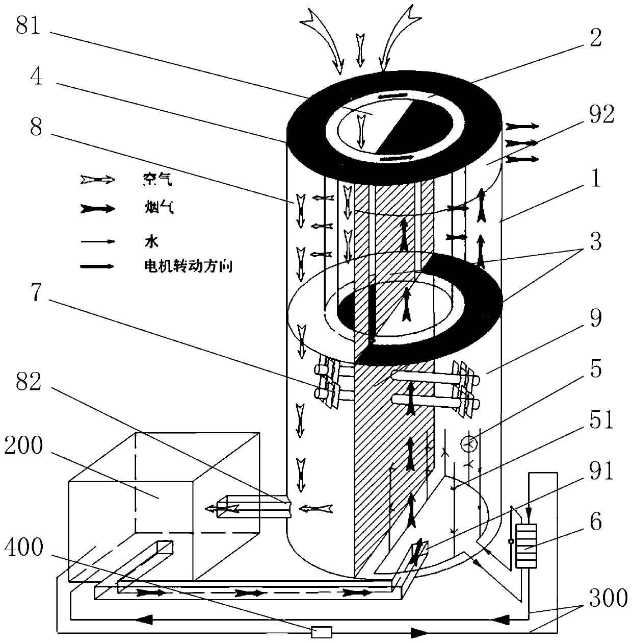
[0022] Such as figure 1 As shown, the flue gas waste heat deep recovery system provided by this embodiment includes a casing 1, a rotor 2, a partition 3, a baffle 4, a spray device 5, a water-to-water heat exchanger 6 and an air-flue gas exchange Heater7. Among them, the housing 1 is in the shape of a vertical thin-walled hollow cylinder; the rotating core 2 is in the shape of a vertical thick-walled hollow cylinder, and the side wall of the rotating core 2 is honeycomb-shaped and the honeycomb opening is horizontal, and the interior is filled with hygroscopic materials. The shaft is set in the upper part of the casing 1, and the rotating core 2 can rotate relative to its own central axis; the partition 3 divides the inner space of the casing 1 and the rotating core 2 into air through the central axis of the casing 1 and the rotating core 2. There are two parts, the flow channel 8 and the flue gas flow channel 9; a plurality of baffles 4 are respectively arranged between the ...

Embodiment 2

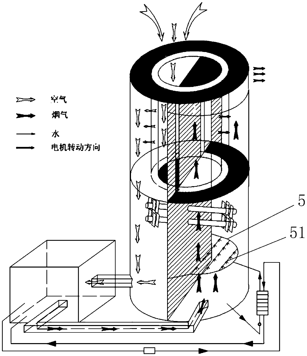
[0026] Such as figure 2 As shown, the flue gas waste heat deep recovery system provided in this embodiment has basically the same structure as that of Embodiment 1, the only difference is that in this embodiment, the liquid distributor 51 of the spray device 5 is arranged above the inlet 91 of the flue gas flow channel. The flue gas and the spray water are exchanged in countercurrent to obtain a better heat exchange effect.

[0027] In the above embodiments, the air-flue gas heat exchanger 7 is arranged below the liquid distributor 51 of the spray device 5, that is, after the flue gas enters the flue gas flow channel 9, it absorbs heat with the air-flue gas heat exchanger 7 first. end heat exchange, and then enter the spray device 5 to exchange heat with spray water.

Embodiment 3

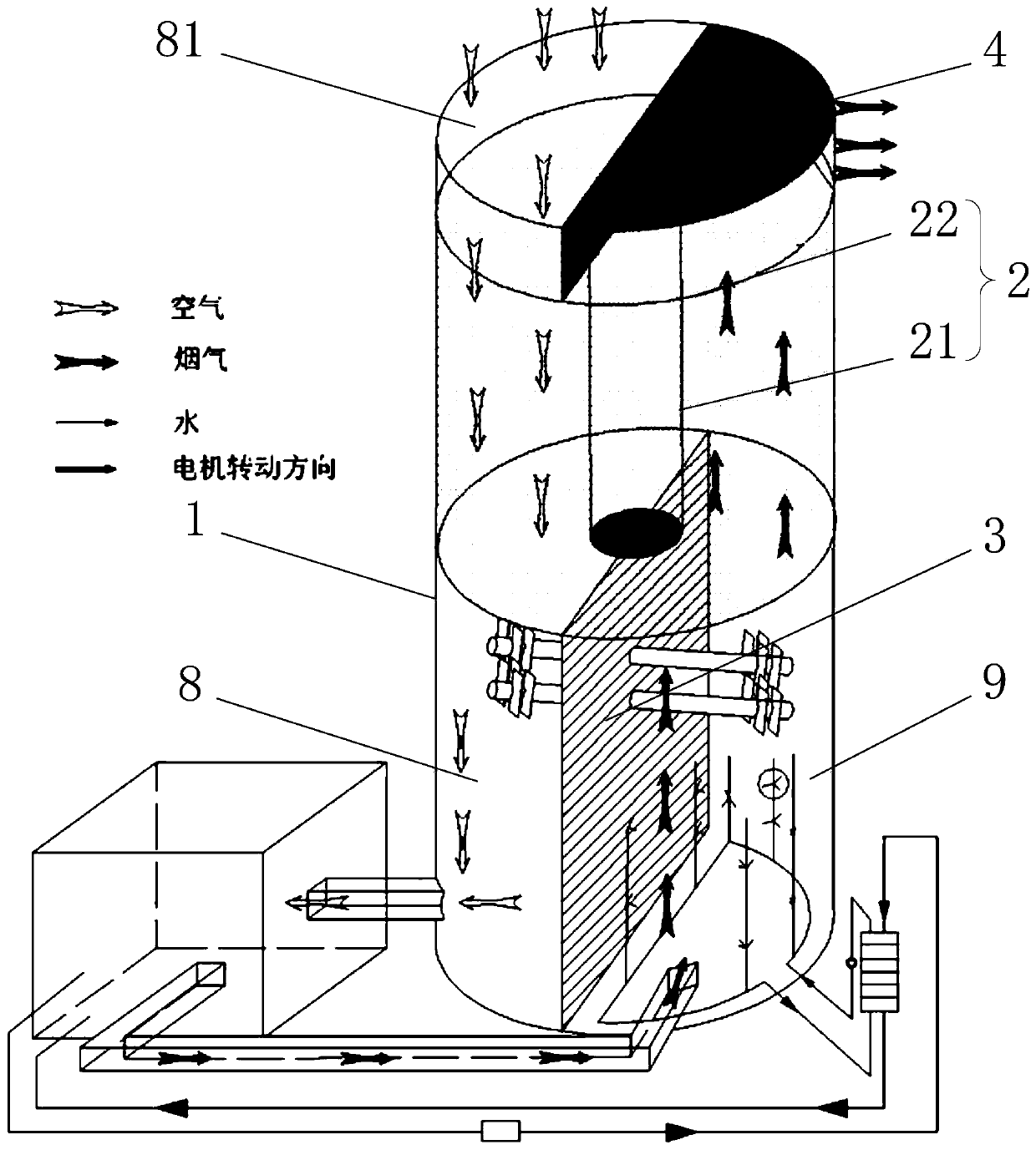
[0029] Such as image 3 As shown, the flue gas waste heat deep recovery system provided in this embodiment has basically the same structure as that of Embodiment 1, the only difference is that the rotating core 2 in this embodiment includes a central rotating shaft 21 and a surrounding runner 22, and the rotating wheel 22 adopts The honeycomb structure and the honeycomb opening are vertical, and the outer diameter of the runner 22 matches the inner diameter of the housing 1; since the air can only flow vertically in the runner 22, the partition 3 is only arranged under the rotor 2 In the housing 1, the inner space of the lower part of the housing 1 is divided into two parts: the air flow channel 8 and the smoke flow channel 9, and the baffle plate 4 only needs to be arranged on the top of the rotor core 2 on the side of the smoke flow channel 9 and Between the top of the housing 1. When the flue gas waste heat deep recovery system of this embodiment is in use, the air passes ...


PUM


Abstract

The invention relates to a deep recovery system for waste heat of flue gas. The recovery system includes a vertical thin-walled hollow cylindrical casing, and a rotating core coaxially arranged on the upper part of the casing and capable of rotating relative to its own central axis is arranged on the The baffle, the baffle plate, the spray device, and the water-to-water heat exchanger connected with the water inlet and outlet of the spray device in the shell and through the central axis of the shell and the rotating core; the rotating core is vertical Type thick-walled hollow cylinder, the longitudinal section of the side wall of the rotor is honeycomb-shaped, and filled with hygroscopic material inside; the partition divides the inner space of the shell and the rotor into two parts: the air flow channel and the smoke flow channel; A plurality of baffles are arranged respectively between the top of the housing and the top of the rotating core, between the top of the rotating core on the side of the smoke flow channel and the top of the partition, and between the bottom of the rotating core on the side of the air flow channel and the top of the partition. Between the plates, and between the bottom of the rotating core on the side of the flue gas flow channel and the casing; the spray device is arranged in the flue gas flow path at the lower part of the casing.

Description

technical field [0001] The invention belongs to the technical fields of heating, ventilating and air-conditioning and urban heating, and in particular relates to a deep recovery system for flue gas waste heat. Background technique [0002] As a clean and efficient primary energy, the demand for natural gas continues to grow in my country. In 2016, the national natural gas consumption has reached 205.8 billion cubic meters, a year-on-year increase of 6.6%. At the same time, due to the implementation of the "coal-to-gas" policy in the north, natural gas has become the main energy source for heating in winter in the north. At present, gas-fired boilers are the main way of heating in winter, and the exhaust gas temperature of natural gas is generally 80-120°C, which has huge potential for waste heat recovery. Moreover, the thermal efficiency of the boiler gradually increases as the exhaust gas temperature decreases. When the exhaust gas temperature drops to 30-55°C, it enters ...

Claims


Application Information

Patent Timeline
Patent Type & Authority Patents(China)
IPC IPC(8): F23J15/06F23L15/04
CPCF23J15/06F23J2219/80F23L7/005F23L15/04F24H8/00F24H9/0084F28D19/045F28D21/0015Y02B30/00Y02E20/34Y02P80/15
Inventor 江亿刘晓华徐熙张世钢
Owner TSINGHUA UNIV
Why Eureka
Try Eureka