A boiler flue gas waste heat recovery device

A technology of waste heat recovery device and boiler flue gas, which is applied in the field of waste heat recovery device and boiler flue gas waste heat recovery device, can solve the problems of high system complexity, achieve the effects of improving matching characteristics, increasing temperature and humidity levels, and improving energy utilization efficiency

Active Publication Date: 2019-01-04
TSINGHUA UNIV
View PDF2 Cites 0 Cited by
  • Summary
  • Abstract
  • Description
  • Claims
  • Application Information

AI Technical Summary

Problems solved by technology

However, the current flue gas waste heat recovery system usually has a high degree of complexity in the process of recovering flue gas sensible heat and latent heat at the same time. How to further build a simple and compact flue gas waste heat recovery system to realize efficient recovery and utilization of flue gas heat , which is an important problem to be solved to improve the utilization efficiency of natural gas in the actual heating system

Method used


Image

  • A boiler flue gas waste heat recovery device
  • A boiler flue gas waste heat recovery device
  • A boiler flue gas waste heat recovery device

Examples


Embodiment 1

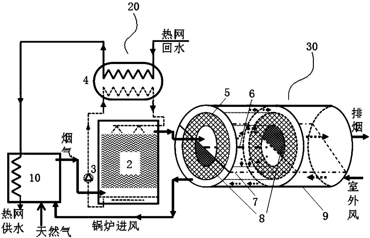
[0018] figure 1 A boiler flue gas waste heat recovery device using a solid moisture absorbent according to Embodiment 1 of the present invention is shown. The device includes a gas boiler 10 , a direct spray type flue gas heat recovery unit 20 and a solid moisture absorbent heat recovery unit 30 .

[0019] Wherein, the direct spray flue gas heat recovery unit 20 includes a flue gas-water spray tower 2 , a circulating water pump 3 and a water-water heat exchanger 4 . The solution outlet at the bottom of the flue gas-water spray tower 2 is connected to the spray inlet of the flue gas-water spray tower 2 through the circulating water pump 3 and the water-water heat exchanger 4, and the heat exchange end of the water-water heat exchanger 4 enters the The water pipe is connected to the return water of the heating network, and the water outlet pipe is connected to the heating network for water supply after passing through the gas boiler 10 .

[0020] Such as figure 1 , figure 2 ...

Embodiment 2

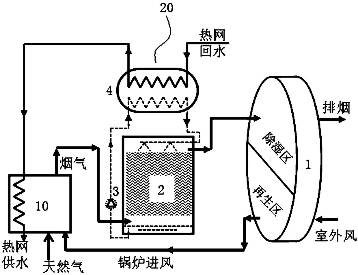
[0030] image 3 The boiler flue gas waste heat recovery device provided according to Embodiment 2 of the present invention using a solid moisture absorbent runner is shown. Compared with the boiler flue gas waste heat recovery device provided in Embodiment 1, the difference between this flue gas waste heat recovery device is only that: The solid moisture absorbent runner 1 realizes the total heat recovery process between the flue gas and the outdoor wind, that is, the flue gas flowing out from the top of the flue gas-water spray tower 2 directly flows through the dehumidification area of ​​the solid moisture absorbent runner 1, and The solid hygroscopic agent performs heat and mass exchange, and the heat and moisture in the flue gas are absorbed by the solid hygroscopic agent to become smoke exhaust; the outdoor wind flows through the regeneration area of ​​the solid hygroscopic agent runner 1, and performs heat and mass exchange with the solid hygroscopic agent. , after being...


PUM


Abstract

The invention relates to a boiler flue gas waste heat recovery device. The device comprises a direct spraying type flue gas heat recovery unit communicated with a flue gas outlet of a boiler, and a rotary solid moisture absorption agent heat recovery unit; the flue gas flowing out of the direct spraying type flue gas heat recovery unit is firstly subjected to heat and mass transfer with the solid moisture absorption agent heat recovery unit, and heat and moisture of the flue gas are absorbed by the solid moisture absorption agent heat recovery unit to become exhaust smoke; then the solid moisture absorption agent heat recovery unit is rotated to be subjected to heat and mass transfer with outdoor air, and the outdoor air is heated and humidified by the solid moisture absorption agent heat recovery unit to form boiler inflow air and is sent to the boiler. The direct spraying type flue gas heat recovery unit is used for directly making contact with flue gas for heat recovery, and the solid moisture absorption agent heat recovery unit is used for carrying out heat and mass transfer with the flue gas and the outdoor air, so that the latent heat of water vapor in the flue gas is effectively recycled; the recycled heat is used for preheating returned water of a heat supply network, so that the gradient recycling of the heat of the flue gas is achieved, and the energy utilization efficiency of a heat supply system of the boiler is effectively improved.

Description

technical field [0001] The invention relates to a waste heat recovery device, in particular to a boiler flue gas waste heat recovery device, which belongs to the field of HVAC systems. Background technique [0002] Heating energy consumption in northern cities and towns is an important component of my country's building energy consumption, accounting for about 40% of the current total building energy consumption. How to effectively reduce heating energy consumption in northern cities and towns is an important issue facing the development of ecological civilization construction and building energy conservation. problem. With the promotion of natural gas clean heating, natural gas boiler heating and gas-driven combined heat and power heating have been more and more used in northern my country, becoming an important form of heat source for central heating systems in northern cities and towns. Judging from the chemical composition of natural gas, the flue gas formed after combus...

Claims


Application Information

Patent Timeline
Patent Type & Authority Patents(China)
IPC IPC(8): F23L15/00F24H1/00
CPCF23L15/00F24H1/00Y02E20/34
Inventor 刘晓华张涛符黄喜江亿
Owner TSINGHUA UNIV
Why Eureka
Try Eureka