
High-power semispherical mutual coupling compensation medium antenna housing for phased-array antenna

A technology for phased array antennas and dielectric antennas, applied in antennas, radiating unit covers, electrical components, etc., can solve the problems of being unsuitable for high-power applications, difficult to process, and unable to withstand air pressure, etc., to achieve simple structure, easy processing, The effect of improving power capacity

Inactive Publication Date: 2010-05-12
SOUTHWEST JIAOTONG UNIV
View PDF1 Cites 6 Cited by
  • Summary
  • Abstract
  • Description
  • Claims
  • Application Information

AI Technical Summary

Problems solved by technology

However, this structure is not easy to process and cannot withstand high air pressure, so it is not suitable for high power applications that need to increase power capacity through inflation or vacuum

Method used


Image

  • High-power semispherical mutual coupling compensation medium antenna housing for phased-array antenna
  • High-power semispherical mutual coupling compensation medium antenna housing for phased-array antenna
  • High-power semispherical mutual coupling compensation medium antenna housing for phased-array antenna

Examples


Embodiment approach

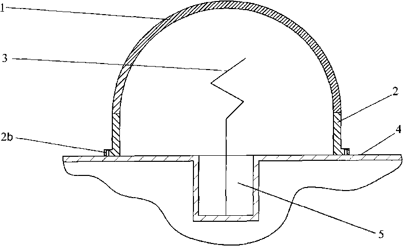
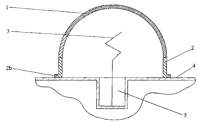
[0019] figure 1 It is shown that one embodiment of the present invention is: a high-power hemispherical mutual coupling compensation dielectric radome for phased array antennas, which consists of: a hemispherical shell or a spherical crown with a high dielectric constant dielectric cover 1. The edge of the dielectric cover 1 is connected to the top of the circular high dielectric constant base 2, and the bottom of the base 2 is fixed on the aperture surface 4 of the phased array antenna.

[0020] The lower part of the base 2 in this example protrudes outward to form a boss 2b, and the base 2 is screwed on the aperture surface 4 of the phased array antenna through the boss 2b. The thickness of the medium cover 1 in this example is uniform everywhere.

[0021] The dielectric cover in this example is used for circularly polarized phased array antennas, and a dielectric cover is used on each element antenna in the phased array.

[0022] The specific size and structure of the die...

Embodiment 2

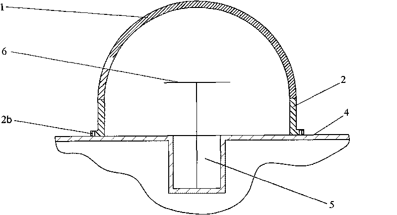
[0027] figure 2 It is shown that this embodiment is basically the same as Embodiment 1, the difference is only that the dielectric cover is applied to a linearly polarized phased array antenna. The figure shows that the dielectric cover is used for a unit antenna in the array; the linearly polarized unit antenna 6 is placed in the center of the dielectric cover.

[0028] When the microwave operating frequency is 4GHz, the specific dimensions of this embodiment are: the linearly polarized phased array antenna adopts a rectangular grid with a unit spacing of 0.65 wavelengths; the dielectric cover 1 is a spherical crown with an inner diameter of 21mm and a wall thickness of 1mm. The height is 16.55mm; the inner diameter of the base 2 of the dielectric cover is 21mm, the wall thickness is 1mm, and the height is 7.5mm; the wall thickness (width) of the boss 2b is 6mm, and the height is 2mm.

[0029]The data simulation results show that in this embodiment, under the condition that...


PUM


Abstract

The invention discloses a high-power semispherical mutual coupling compensation medium antenna housing for a phased-array antenna, which comprises a semispherical or spherical crown-shaped high-dielectric constant medium housing cap (1), wherein the cap edge of the medium housing cap (1) is connected with the top part of an annular high-dielectric constant base (2); and the bottom part of the base (2) is fixed on an aperture plane (4) of the phased-array antenna. The medium antenna housing is used for the mutual coupling impedance compensation of the phased-array antenna, can match the impedance of the phased-array antenna and the impedance of free space, serve as an antenna housing to seal the phased-array antenna and withstand high internal air pressure, has high power capacity, is suitable for various polarized alloy antennae and has simple structure and easy processing.

Description

technical field [0001] The invention relates to the field of phased array antennas, in particular to the field of mutual coupling compensation of phased array antennas, in particular to a high-power hemispherical dielectric radome with the function of mutual coupling compensation. Background technique [0002] An antenna is an exchange device between a power source and free space. If the antenna is not matched to free space, the power will be reflected towards the source, resulting in a loss of radiated power, and a standing wave will be generated in the antenna feedline. The non-beam scanning antenna can be easily adjusted to a matching state at a point close to the matching source. Even if it is not matched, it only affects the radiation power level, and the pattern does not change. However, in beam scanning antennas such as phased arrays, due to the mutual coupling between the element antennas, the impedance of the radiating element changes with the beam scanning, and so...

Claims


Application Information

Patent Timeline
IPC IPC(8): H01Q3/30H01Q1/42
Inventor 张健穹刘庆想李相强赵柳
Owner SOUTHWEST JIAOTONG UNIV
Learn More