Antenna, low-frequency radiation unit and radiation arm

A technology of radiating element and radiating arm, applied in the structural form of radiating element, antenna, slot antenna, etc., can solve the problem of easily deteriorating the impedance characteristics of low-frequency radiating element

Active Publication Date: 2021-01-01
COMBA TELECOM TECH (GUANGZHOU) CO LTD +1
View PDF8 Cites 6 Cited by
  • Summary
  • Abstract
  • Description
  • Claims
  • Application Information

AI Technical Summary

Problems solved by technology

[0003] Based on this, it is necessary to provide an antenna, a low-frequency radiation unit and a radiation

Method used


Image

  • Antenna, low-frequency radiation unit and radiation arm
  • Antenna, low-frequency radiation unit and radiation arm
  • Antenna, low-frequency radiation unit and radiation arm

Examples


Embodiment Construction

[0044]In order to make the above objects, features and advantages of the present invention more comprehensible, specific implementations of the present invention will be described in detail below in conjunction with the accompanying drawings. In the following description, numerous specific details are set forth in order to provide a thorough understanding of the present invention. However, the present invention can be implemented in many other ways different from those described here, and those skilled in the art can make similar improvements without departing from the connotation of the present invention, so the present invention is not limited by the specific embodiments disclosed below.

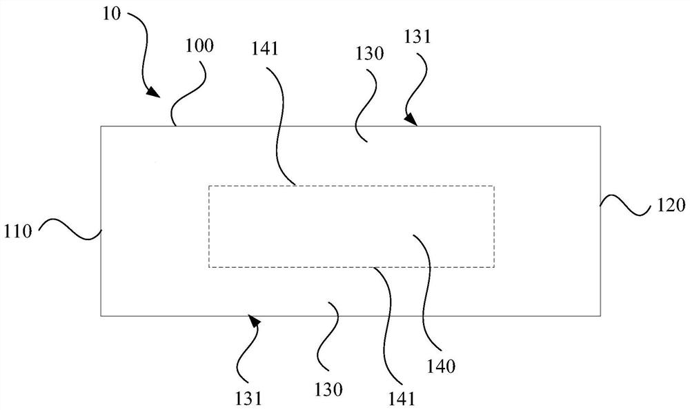
[0045] like figure 1 and figure 2 As shown, in one embodiment, a radiating arm 10 is provided, which can be applied to a low-frequency radiating unit of an antenna. The radiating arm 10 includes a radiating body 100 , the radiating body 100 has a feeding end 110 , an end 120 opposite to...


PUM


Abstract

The invention relates to an antenna, a low-frequency radiation unit and a radiation arm, the radiation arm comprises a radiation body, the radiation body is provided with a feed end, a tail end and aconductor section, the tail end and the feed end are oppositely arranged at an interval, the conductor section is arranged between the feed end and the tail end, and a scattering suppression structureis arranged in the contour area of the conductor section. The scattering suppression structure is provided with a current transmission path arranged corresponding to the conductor section, and the current transmission path is continuously arranged. The scattering suppression structure not only can suppress the intensity of the scattering signal and reduce the influence of the scattering signal onthe performance index of the high-frequency radiation unit, but also can reduce the influence on the impedance characteristic of the low-frequency radiation unit, so that the low-frequency radiationunit can keep a good matching characteristic.

Description

technical field [0001] The invention relates to the technical field of mobile communication, in particular to an antenna, a low-frequency radiation unit and a radiation arm. Background technique [0002] With the rapid development of mobile communication technology, the antenna is also further developed towards miniaturization. In order to reduce the size of the antenna, the radiating elements of different frequency bands can be placed close to each other to reduce the physical size of the antenna. In this way, the high-frequency radiation unit will excite the induced current in the low-frequency radiation unit in its working state, especially the induced current located in the radiation arm of the low-frequency radiation unit is in the open electromagnetic field boundary, which will generate scattered signals and affect the high-frequency radiation. Unit performance metrics. The traditional method is to connect a choke structure in series with the radiating arm of the low...

Claims


Application Information

Patent Timeline
IPC IPC(8): H01Q1/36H01Q1/50H01Q1/52H01Q13/10
CPCH01Q1/36H01Q1/50H01Q1/521H01Q13/10
Inventor 赖展军徐慧俊薛锋章苏国生李明超刘培涛王强王宇郑之伦
Owner COMBA TELECOM TECH (GUANGZHOU) CO LTD
Why Eureka
Try Eureka