Motor

一种电动机、转动机构的技术,应用在电动机领域,能够解决难以适当控制第一及第二转子相位、电动机控制处理复杂化、不能控制相位差等问题,达到扩大转速范围及转矩范围、抑制复杂化、实现小型化的效果

Inactive Publication Date: 2009-05-20
HONDA MOTOR CO LTD
View PDF5 Cites 1 Cited by
  • Summary
  • Abstract
  • Description
  • Claims
  • Application Information

AI Technical Summary

Problems solved by technology

[0005] In addition, in the electric motor in an example of the above-mentioned prior art, for example, in the case of controlling the phase difference between the first and second rotors according to the rotational speed of the motor, only in the operating state of the motor, that is, the state in which the centrifugal force acts according to the rotational speed The phase difference between the first and second rotors can be controlled, but there is a problem that the phase difference cannot be controlled at an appropriate moment including the stop state of the motor
In addition, as in the case where the electric motor is used as a drive source and mounted on a vehicle, in a state where external vibrations tend to act on the electric motor, it may be difficult to properly control the first and second rotors only by the action of centrifugal force. Phase difference problem
Also, in this case, since the phase difference is not limited to the control of the power supply voltage fluctuation in the power supply of the motor, for example, there may be a problem that the magnitude relationship between the power supply voltage and the reverse voltage of the motor is reversed.
[0006] In addition, for example, in the case of controlling the phase difference between the first and second rotors based on the speed of the rotating magnetic field generated in the stator, the speed of the rotating magnetic field is changed, so the problem of complicated control processing of the motor occurs.

Method used


Image

  • Motor
  • Motor
  • Motor

Examples


no. 1 approach

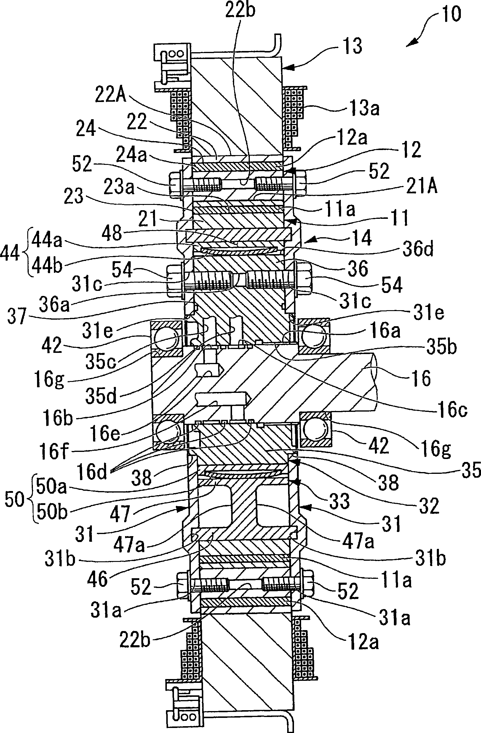
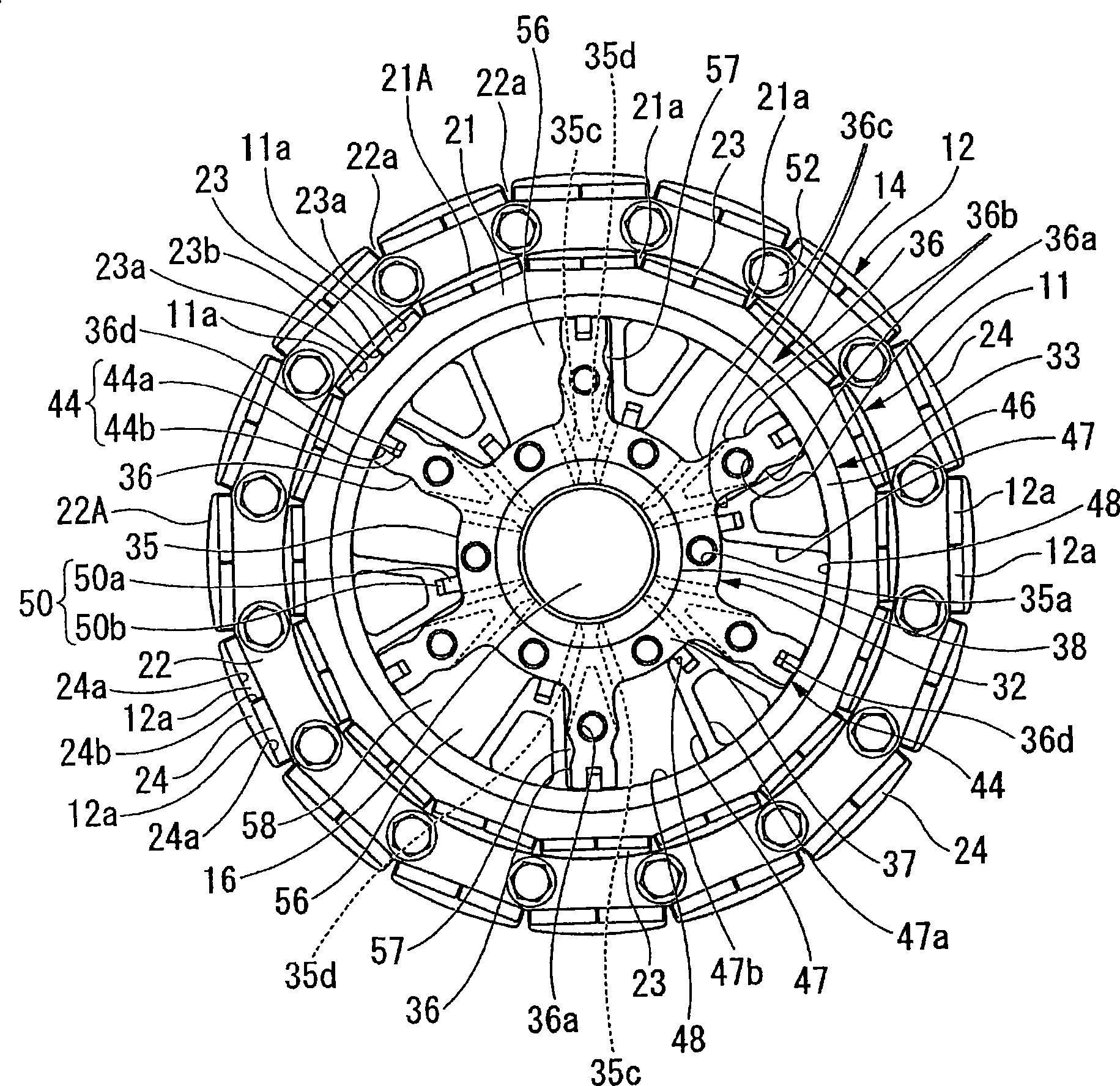
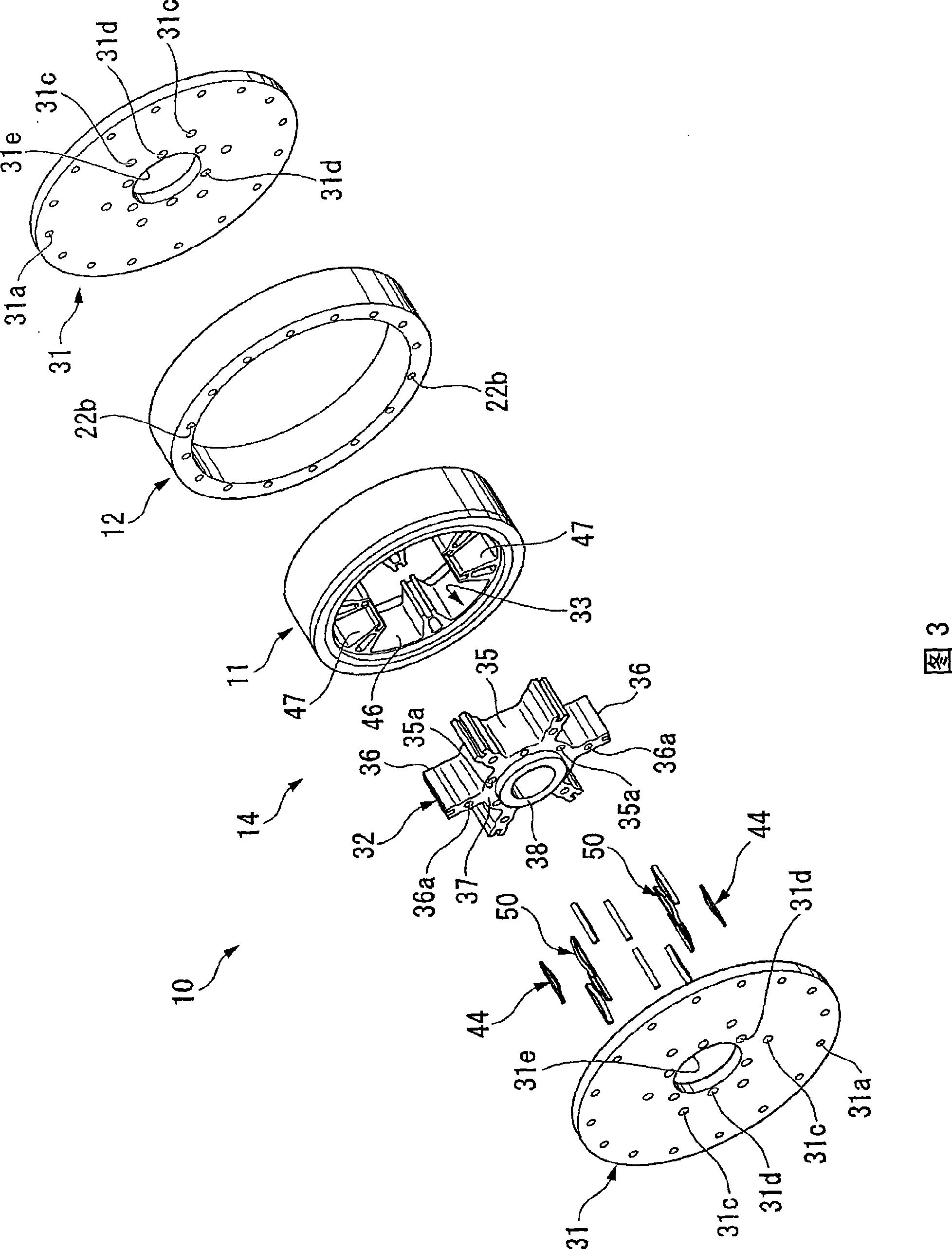
[0097] Below, refer to Figure 1 to Figure 10B A motor according to the first embodiment of the present invention will be described.

[0098] The electric motor 10 of the present embodiment is as follows figure 1 3 shows a brushless DC motor including: a substantially annular inner circumference side rotor 11 rotatably provided with the rotation axis of the motor 10 as the center; and a substantially annular annular outer circumference side rotor 12 With respect to the radially outer side of the inner circumference side rotor 11, the inner circumference side rotor 11 is provided so as to be rotatable with the coaxial rotation axis as the center, and is provided corresponding to the position in the rotation axis direction; Polyphase of the rotating magnetic field of the side rotor 12 figure 1 The shown stator winding 13a; the turning mechanism (turning device) 14, which is connected to the inner rotor 11 and the outer rotor 12, and is connected to the hydraulic pressure (flui...

no. 2 approach

[0153] Second, the main reference Figure 11 and Figure 12 , the motor according to the second embodiment of the present invention will be described focusing on the parts different from the above-described first embodiment. In addition, the same code|symbol is attached|subjected to the same part as the said 1st Embodiment, and the description is abbreviate|omitted.

[0154] In this embodiment, a part of the rotation mechanism 14 is changed from the above-described first embodiment. First, as Figure 11 As shown, one of the transmission plates 31 is fixed to the outer peripheral side rotor 12 by bolts 52, . The hub portion 35 is further fixed to the blade portion 36 of the blade rotor 32 by bolts 54 , . . . , 54 .

[0155] In contrast, the annular transmission plate 61 is disposed on the opposite side in the axial direction of the transmission plate 31 so as to cover a part of the outer peripheral sides of the outer peripheral side rotor 12 and the inner peripheral side ro...

no. 3 approach

[0161] Second, the main reference Figure 13 , the motor according to the third embodiment of the present invention will be described focusing on the differences from the first embodiment described above. In addition, the same code|symbol is attached|subjected to the same part as the said 1st Embodiment, and the description is abbreviate|omitted.

[0162] In this embodiment, the rotation mechanism 70 different from that of the above-described first embodiment is used.

[0163] The turning mechanism 70 of the present embodiment includes a pair of annular transmission plates (first members) 71 and 71 that are fixed to both sides in the axial direction of the outer circumference side rotor 12 so as to cover the space inside the outer circumference side rotor 12 ; The supporting member 73 that is integrally provided on the one transmission plate 71 and supported by the output shaft 72 of the electric motor 10; 74; An inner rotor body 75 having the same structure as the inner rot...


PUM


Abstract

A motor includes rotation means having a first member arranged as a rotatable unitary block with an outer circumference side rotor and a second member arranged as a rotatable unitary block with an inner circumference side rotor. The first member and the second member forms a pressure chamber inside the inner circumference side rotor. By supplying a work fluid into the pressure chamber, it is possible to change the relative phase between the inner circumference side rotor and the outer circumference side rotor.

Description

technical field [0001] The present invention relates to electric motors. [0002] This application takes Japanese Patent Application Nos. 2006-060064, 2006-060065, 2006-060066, and 2006-060067 as basic applications, and incorporates the contents thereof. Background technique [0003] Conventionally, a motor is known that includes, for example, first and second rotors arranged concentrically around a rotation axis of the motor, and controls the first and second rotors according to the rotational speed of the motor or the speed of the rotating magnetic field generated by the stator. The relative position in the circumferential direction of the second rotor is a phase difference (for example, refer to Patent Document 1). [0004] In this motor, for example, when the phase difference between the first and second rotors is controlled according to the rotational speed of the motor, the circumferential directions of the first and second rotors are changed through a member that is ...

Claims


Application Information

Patent Timeline
Patent Type & Authority Applications(China)
IPC IPC(8): H02K1/27H02K16/02
CPCY02T10/641H02K1/276H02K7/12H02K16/02H02K21/029H02K21/16
Inventor 岩田和之佐藤浩光森下尚久新崎知河村保藤冈征人
Owner HONDA MOTOR CO LTD
Why Eureka
Try Eureka