Pressure-variable inflator

A pump and pressure technology, applied in the field of pumps, can solve problems such as inability to effectively carry out large volume or high-pressure air intake, easy to touch by mistake, etc.

Inactive Publication Date: 2009-07-29
吴树木
View PDF1 Cites 8 Cited by
  • Summary
  • Abstract
  • Description
  • Claims
  • Application Information

AI Technical Summary

Problems solved by technology

[0005] The technical problem to be solved by the variable pressure inflator of the present invention is that the conventional adjustment assembly is installed on the base, and when the operator pumps air, it is easy to touch the adjustment assembly by mistake, and it is impossible to effectively carry out large volume or high pressure air intake.

Method used


Image

  • Pressure-variable inflator
  • Pressure-variable inflator
  • Pressure-variable inflator

Examples


Embodiment Construction

[0028] Regarding the technology, means and effects used in the present invention, a preferred embodiment is given and described in detail below with drawings, which are for illustration purposes only, and are not limited by this structure in the patent application.

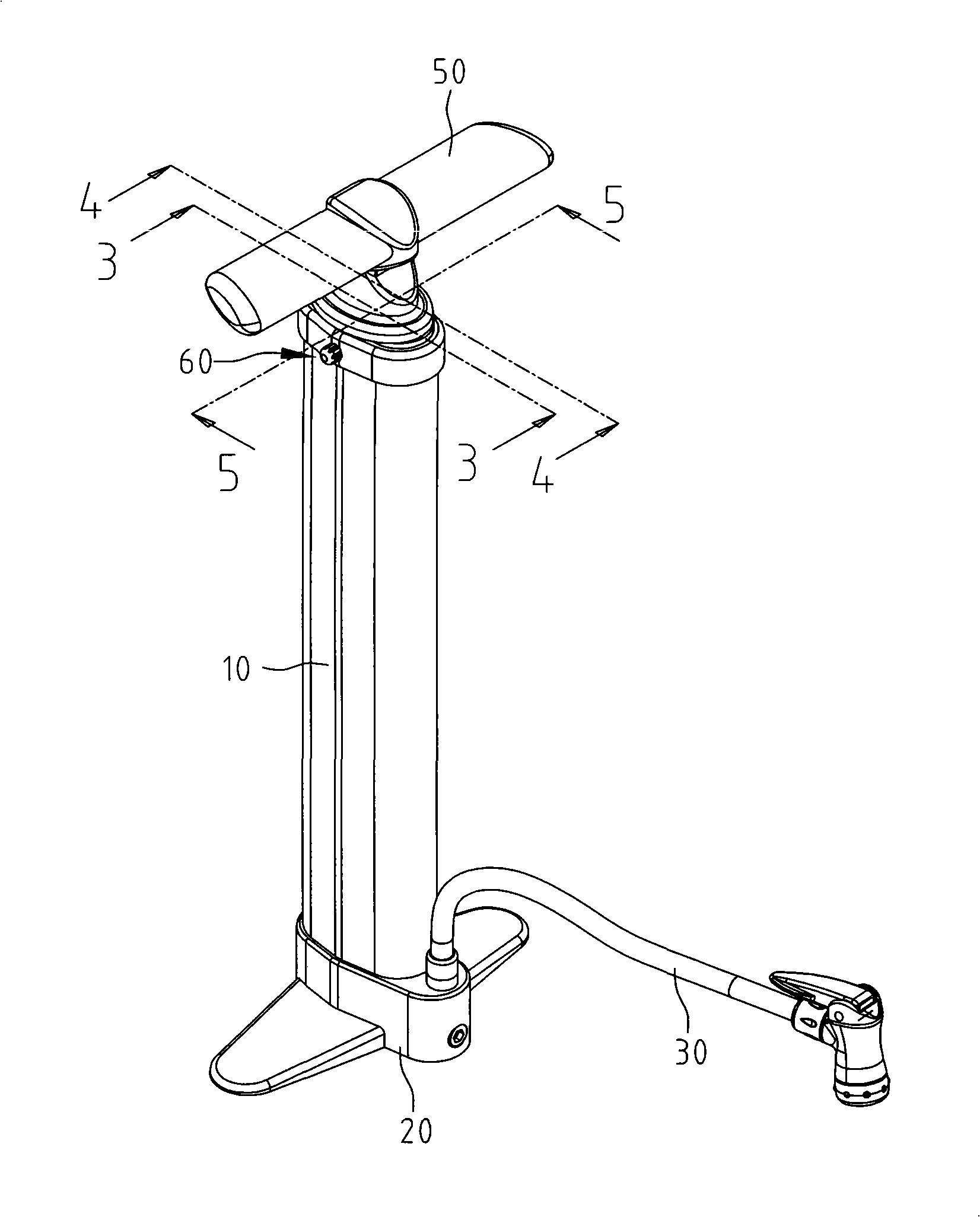
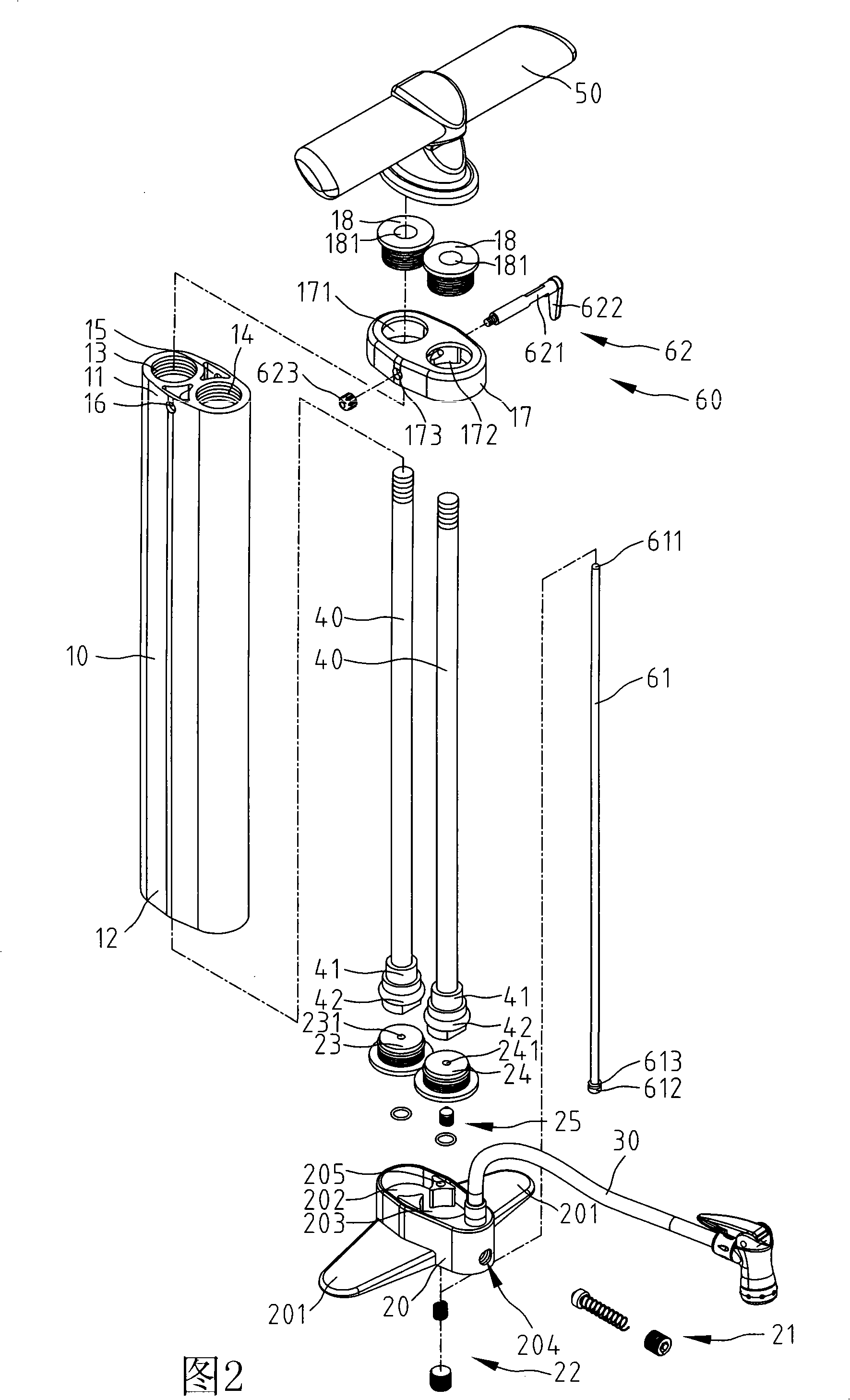
[0029] refer to figure 1 2 is a three-dimensional appearance view and a three-dimensional exploded view of the first embodiment of the pump of the present invention. The pump of the present invention includes a cylinder body 10 , a base 20 , a hose 30 , two piston rods 40 , a handle 50 and a control device 60 .

[0030] The barrel 10 includes a first end 11 and a second end 12 , the first end 11 is combined with the base 20 , and the second end 12 is combined with the handle 50 . The cylinder 10 also includes two air chambers 13, 14 and an accommodating space 15, both of which axially pass through the first end 11 and the second end 12, wherein the first end 11 is also provided with a hole 16, the said The hole ...


PUM


Abstract

The invention relates to an inflator with variable pressure, which comprises a cylinder body that is internally provided with two air chambers and a holding space; wherein, the two air chambers of the cylinder body are respectively and internally provided with a piston rod, and the two piston rods pass and extend through a first end of the cylinder body; a second end of the cylinder body is provided with a base which comprises an air inlet channel and an air escape channel that are communicated with each other; a control device comprises a control group and an air escape rod, wherein, the control group is arranged inside the cylinder body along the radial direction, so as to ensure the operator to have an absolute safe space when in air inflating and not to affect air inlet when the control group is contacted by mistake; the air escape rod is held inside the holding space; the control group is controlled to selectively press the air escape rod to further open or close the air escape channel, thus providing large air flow inlet and high pressure air inlet for selection.

Description

technical field [0001] The invention relates to an air pump, in particular to an air pump which changes the pumping volume and further changes the pressure. Background technique [0002] With reference to my country's Patent Announcement No. CN2539849 No. CN2539849 Inflator with high pressure and large air output, inner and outer cylinders and hollow inflator rods between the inner and outer cylinders are arranged on the base. One-way air intake valves are provided between the cylinders, one-way air intake valves are provided between the inner side of the inflating rod and the fixed piston on the top of the inner cylinder body, one-way valves are set at the upper and lower ends of the inner cylinder body, and the inner cylinders are respectively installed in the base. The body and the outer cylinder extend to the channel of the air outlet. A one-way valve is installed in each channel, and an adjustment component that can control the opening and closing of the channel is instal...

Claims


Application Information

Patent Timeline
Patent Type & Authority Applications(China)
IPC IPC(8): F04B33/00F04B49/00
Inventor 吴树木
Owner 吴树木
Why Eureka
Try Eureka