Anesthesia device with stand-alone vaporizer apparatus

A technology of vaporizers and anesthesia machines, which is applied in the direction of respirators, drug devices, and other medical devices, and can solve problems such as low efficiency

Inactive Publication Date: 2009-08-05
GENERAL ELECTRIC CO
View PDF0 Cites 18 Cited by
  • Summary
  • Abstract
  • Description
  • Claims
  • Application Information

AI Technical Summary

Problems solved by technology

It can be seen that operating a control system that includes two distinct, remotely located user interfaces may be less efficient than a control system employing a single interface

Method used


Image

  • Anesthesia device with stand-alone vaporizer apparatus

Examples


Embodiment Construction

[0013] In the following detailed description, reference is made to the accompanying drawings, which form a part hereof, and in which are shown by way of illustration specific embodiments that may be practiced. These embodiments are described in sufficient detail to enable those skilled in the art to practice them, and it is to be understood that other embodiments may be utilized and that logical, mechanical, electrical, and Other changes can be made without departing from the scope of these embodiments. Accordingly, the following detailed description is not intended to limit the scope of the invention.

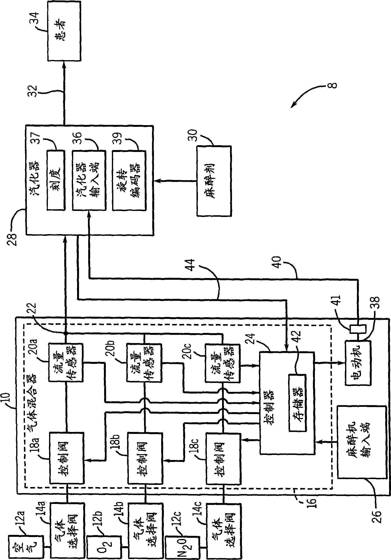
[0014] refer to figure 1 , which schematically depicts an anesthesia system 8 according to one embodiment. The anesthesia system 8 includes an anesthesia machine 10 , a plurality of gas storage devices 12 a , 12 b , and 12 c , and a self-contained vaporizer 28 . The anesthesia machine 10 is shown for illustrative purposes, and it should be understood that other types of ane...


PUM


Abstract

The invention relates to an anesthesia device with an independent vaporizer element. An anesthesia system is disclosed herein. The system includes an anesthesia machine comprising an anesthesia machine input, and a stand-alone vaporizer connected to the anesthesia machine. The stand-alone vaporizer includes a vaporizer input terminal. The stand-alone vaporizer is configured to produce a selectable concentration of an anesthetic agent. The anesthesia machine input terminal and the vaporizer input terminal may be independently implemented to regulate the concentration of the anesthetic agent from the stand-alone vaporizer.

Description

technical field [0001] The subject matter disclosed in this application relates to a system including an anesthesia device and a self-contained vaporizer. Background technique [0002] Traditional anesthesia delivery systems include an anesthesia machine pneumatically coupled to a remotely located self-contained vaporizer. The anesthesia machine typically receives several different gases such as air, O 2 and / or N 2 O, and combine these gases in an optional manner. The self-contained vaporizer introduces a selectable concentration of vaporized anesthetic into the gas mixture. The vaporized anesthetic and gas mixture is then delivered to the patient. [0003] One problem with some conventional anesthesia delivery systems is that the anesthesia machine and vaporizer typically must be controlled through separate interfaces. As an example, the operator typically has to use the first interface provided on the anesthesia machine to set the air, O 2 and N 2 A separate concent...

Claims


Application Information

Patent Timeline
Patent Type & Authority Applications(China)
IPC IPC(8): A61M16/01A61M16/18
CPCA61M16/0051A61M16/18A61M2016/0039A61M2202/0208A61M16/01A61M16/104A61M2202/0283A61M2205/52A61M2205/502A61M16/024
Inventor M·A·索姆R·萨姆J·R·平克特A·容维尔士
Owner GENERAL ELECTRIC CO
Why Eureka
Try Eureka