Straight-fin heat expansion reinforced structure minuteness scale composite phase-change heat fetching method and apparatus

A composite phase-change heat and structure strengthening technology, which is applied in the field of heat dissipation and cooling, can solve the problems of large total heat dissipation capacity, small heat dissipation area, and large heat dissipation area.

Active Publication Date: 2011-02-09
中科微槽群(北京)节能技术开发有限公司
View PDF0 Cites 1 Cited by
  • Summary
  • Abstract
  • Description
  • Claims
  • Application Information

AI Technical Summary

Problems solved by technology

[0003] The purpose of the present invention is to solve the technical defects of the existing air-cooled and water-cooled heat dissipation technologies that require a large heat dissipation area and insufficient heat dissipation capacity, and disclose a method and device for obtaining heat from a micro-scale composite phase change with a straight rib thermal expansion and strengthening structure. The method and The device has no additional power consumption, small heat dissipation area, high heat dissipation heat flux density and large total heat dissipation capacity

Method used


Image

  • Straight-fin heat expansion reinforced structure minuteness scale composite phase-change heat fetching method and apparatus
  • Straight-fin heat expansion reinforced structure minuteness scale composite phase-change heat fetching method and apparatus
  • Straight-fin heat expansion reinforced structure minuteness scale composite phase-change heat fetching method and apparatus

Examples


Embodiment 1

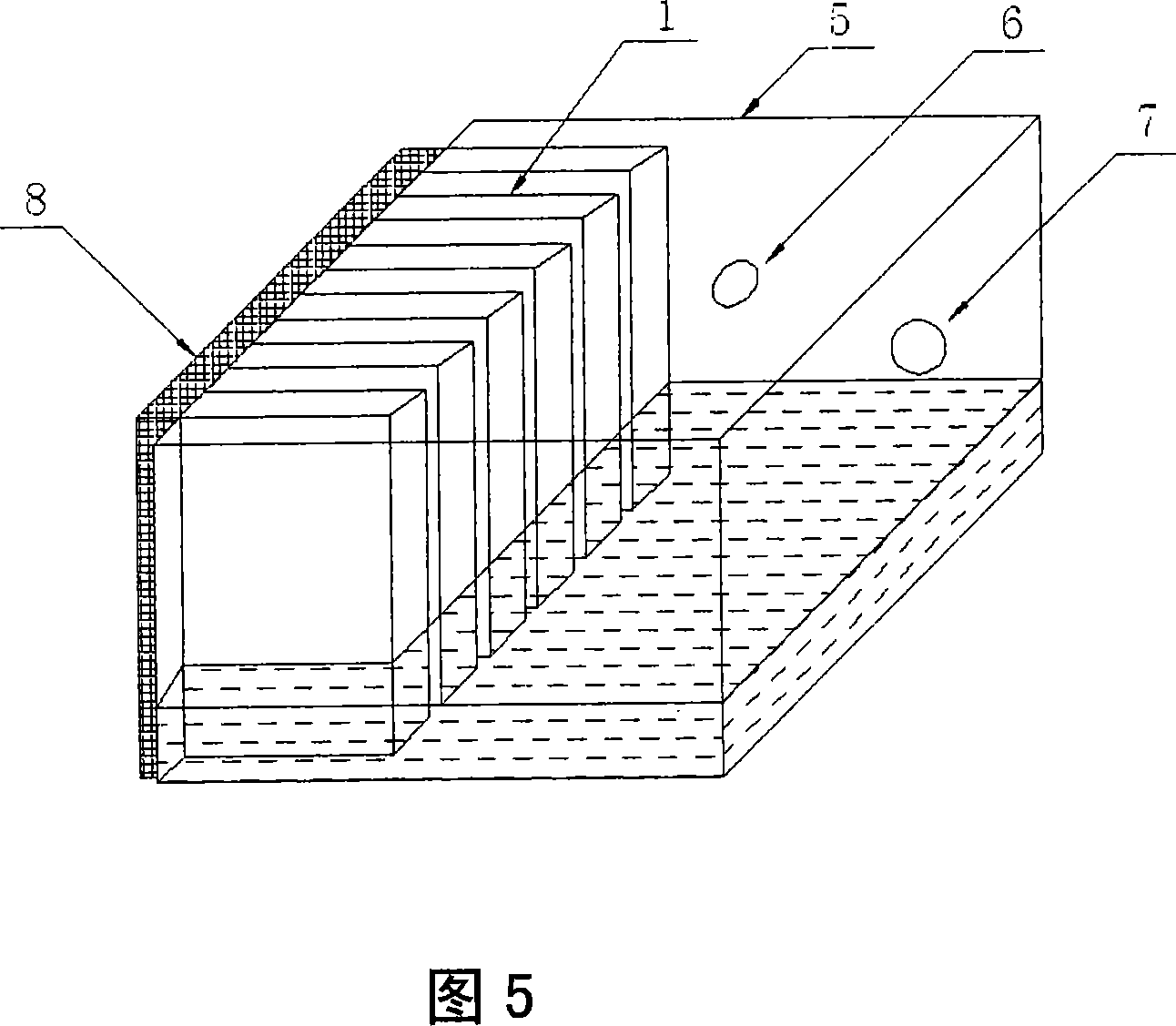
[0029] See Figure 5 , a schematic structural diagram of a micro-scale compound phase change heat extraction device with a straight rib thermal expansion strengthening structure according to the method of the present invention. It includes a heat extractor 5, the heat extractor 5 is a vacuumized sealing body filled with a liquid working medium, the side wall of the heat extractor 5 is a heated wall, and the heated wall is made of a heat-conducting material. The outer surface is closely connected with the outer surface of the heating element 8 through heat-conducting silica gel (silicon grease), and the inner surface of the heated wall is provided with a plurality of straight ribs 1 arranged in parallel longitudinally to form a group of straight ribs. The straight rib group increases the expanded heat exchange area of ​​the inner surface of the heated wall, and increases the rigidity of the heated wall. A plurality of capillary micro-grooves 2 are arranged on the outer surface...

Embodiment 2

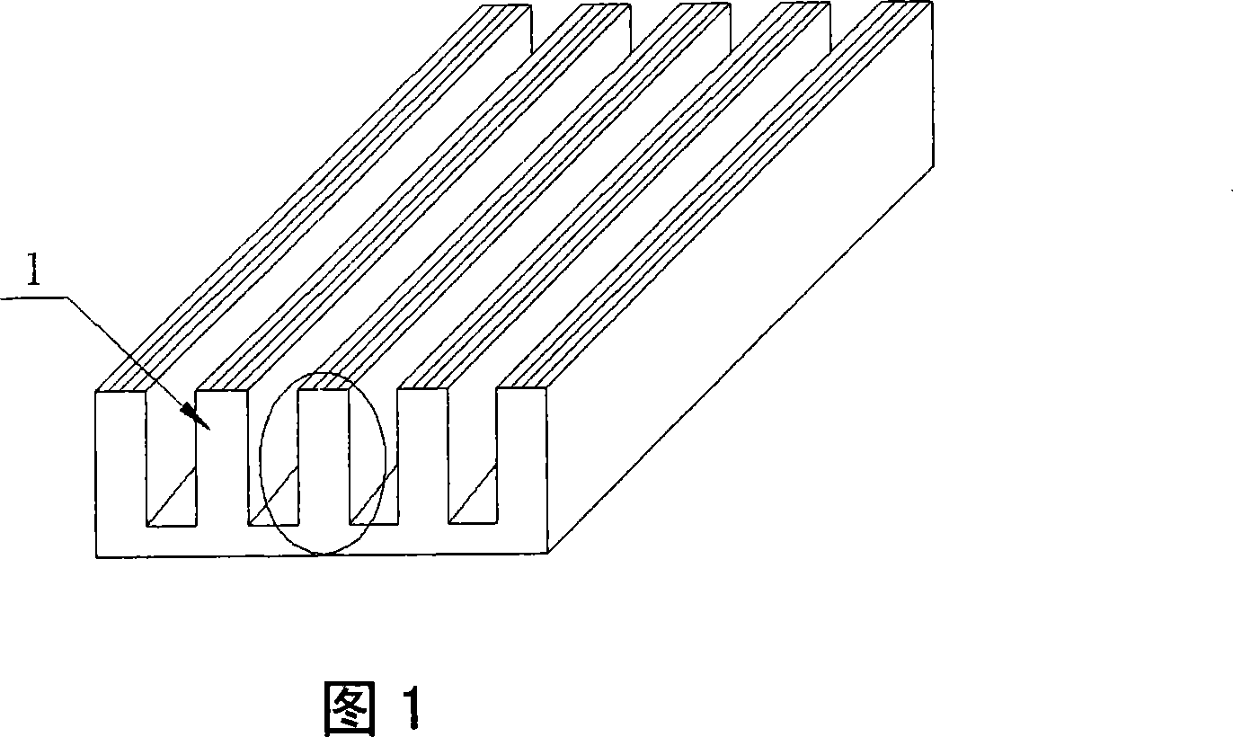
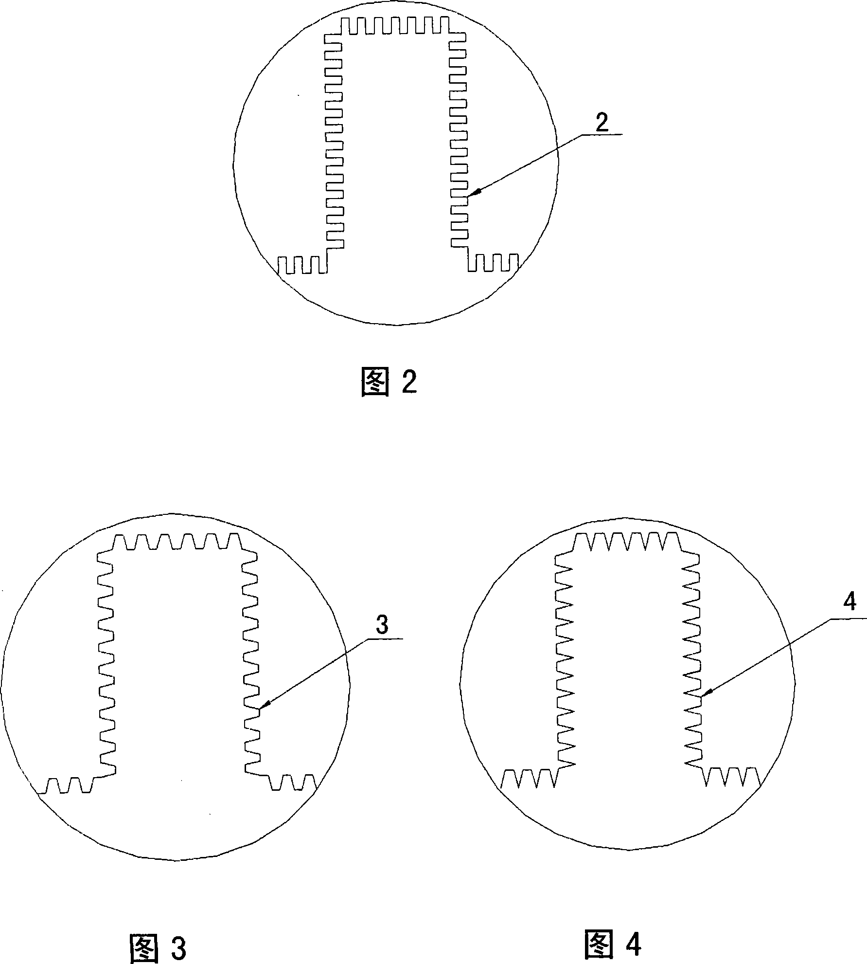
[0037] See figure 1 A plurality of straight ribs 1 are arranged directly on the surface of the heating element 8 or on the outer surface of the heat-conducting material close to the surface of the heating element 8 to form a group of straight ribs, and a plurality of hairs are processed on the outer surface of the straight ribs 1 and the intercostal wall surface The fine channels 2 form micro-groove groups, and this type of heat sink with a structure of straight rib groups and micro-groove groups is called a straight-rib thermally expanded and strengthened structure micro-scale composite phase change heat sink. figure 1 The middle straight ribs 1 are densely arranged longitudinally; figure 2 forfigure 1 In the enlarged view of the middle circle, it can be seen that the capillary micro-channels 2 are also densely arranged longitudinally. The capillary microgroove 2 has a capillary force effect on various working fluids such as absolute ethanol or distilled water. The heat pa...

Embodiment 3

[0039] In this embodiment, the multiple capillary channels 2 of the heat extractor 5 are vertically densely arranged, and the vertically densely arranged capillary channels 2 are arranged with a plurality of transverse capillary channels 2 crosswise. The capillary micro-channels 2 arranged horizontally can ensure the capillary driving force of the liquid working medium flowing along the longitudinal capillary micro-channels 2 under ultra-high heat load, so that the liquid working medium evaporated in the heating area can be replenished in time, thereby further improving the heat extraction capacity . In this embodiment, the groove width of the longitudinal capillary channel 2 is 0.2 mm, the groove depth is 0.5 mm, and the groove spacing is 0.2 mm; the groove width of the transverse capillary micro channel is 0.4 mm, the groove depth is 0.8 mm, and the groove spacing is 5 mm.


PUM


Abstract

The invention relates to a straight-rib heat expansion reinforcing structure micro scale composite phase change heat extraction method and a device, which relates to a heat radiating and cooling technology. The method comprises the following steps: a plurality of straight ribs are arranged on the surface of a heat conducting material on the surface of a heating element or tightly attached on the surface of the heating element to form a straight rib group; and a plurality of capillary microgrooves are arranged on the external surface of the straight ribs and the wall surfaces among the straight ribs to form a capillary microgroove group. Liquid working medium is sucked into the microgrooves by capillary force to lead the heat of the heating element to enter microgroove ways; liquid workingmedium in the microgroove ways brings away the heat of the heating element through a high-strength micro scale evaporation and boiling composite phase change heat-exchange mode after being heated to cool the heating element. The device comprises a vacuumized heat extractor with the straight ribs and the capillary microgrooves on the heating surface thereof, and the heat extractor is filled with liquid working medium. The invention realizes the heat extraction without power consumption through two ways of the heat conduction of the straight ribs and the micro scale composite phase change heat-exchange of the liquid working medium.

Description

technical field [0001] The invention relates to a heat dissipation and cooling method, in particular to a cooling method and a device for high-power electronic, electric and optoelectronic devices. Background technique [0002] At present, there are mainly two ways to cool high-power electronics, electric power and optoelectronic devices: one is to use heat sinks combined with fans for air cooling. Apply heat-conducting silica gel (silicon grease) to reduce thermal resistance, and the fan is placed on the end surface of the heat dissipation fin to use the principle of convection heat transfer to dissipate heat to the environment through the surface of the fin, so as to ensure that the device works within the normal operating temperature range. The main defect of this technology is: with the increase of the power of electronic, electric and optoelectronic devices, the heat dissipation required for the devices to maintain normal operating temperature increases, and the power c...

Claims


Application Information

Patent Timeline
Patent Type & Authority Patents(China)
IPC IPC(8): H05K7/20H01L23/427F28D15/04
Inventor 胡学功肖送连王涛唐大伟
Owner 中科微槽群(北京)节能技术开发有限公司
Why Eureka
Try Eureka