
Apparatus for sensing gearbox shifting positions

A technology for shifting devices and gearboxes, which is applied in the directions of transmission control, transportation and packaging, and components with teeth, etc., and can solve problems such as expensive, complex assembly, and complex space structures

Active Publication Date: 2009-09-02
ZF CV SYST EURO BV
View PDF5 Cites 5 Cited by
  • Summary
  • Abstract
  • Description
  • Claims
  • Application Information

AI Technical Summary

Problems solved by technology

[0004] Disadvantages of the known devices for adjusting gearboxes are the connection technology for connecting the electronic evaluation unit and sensors with the electronic control unit and the complex spatial configuration
Long lines and wide spatial distribution of sensors make faults more prone to occur
Also, assembly is complex and expensive

Method used


Image

  • Apparatus for sensing gearbox shifting positions
  • Apparatus for sensing gearbox shifting positions
  • Apparatus for sensing gearbox shifting positions

Examples


Embodiment Construction

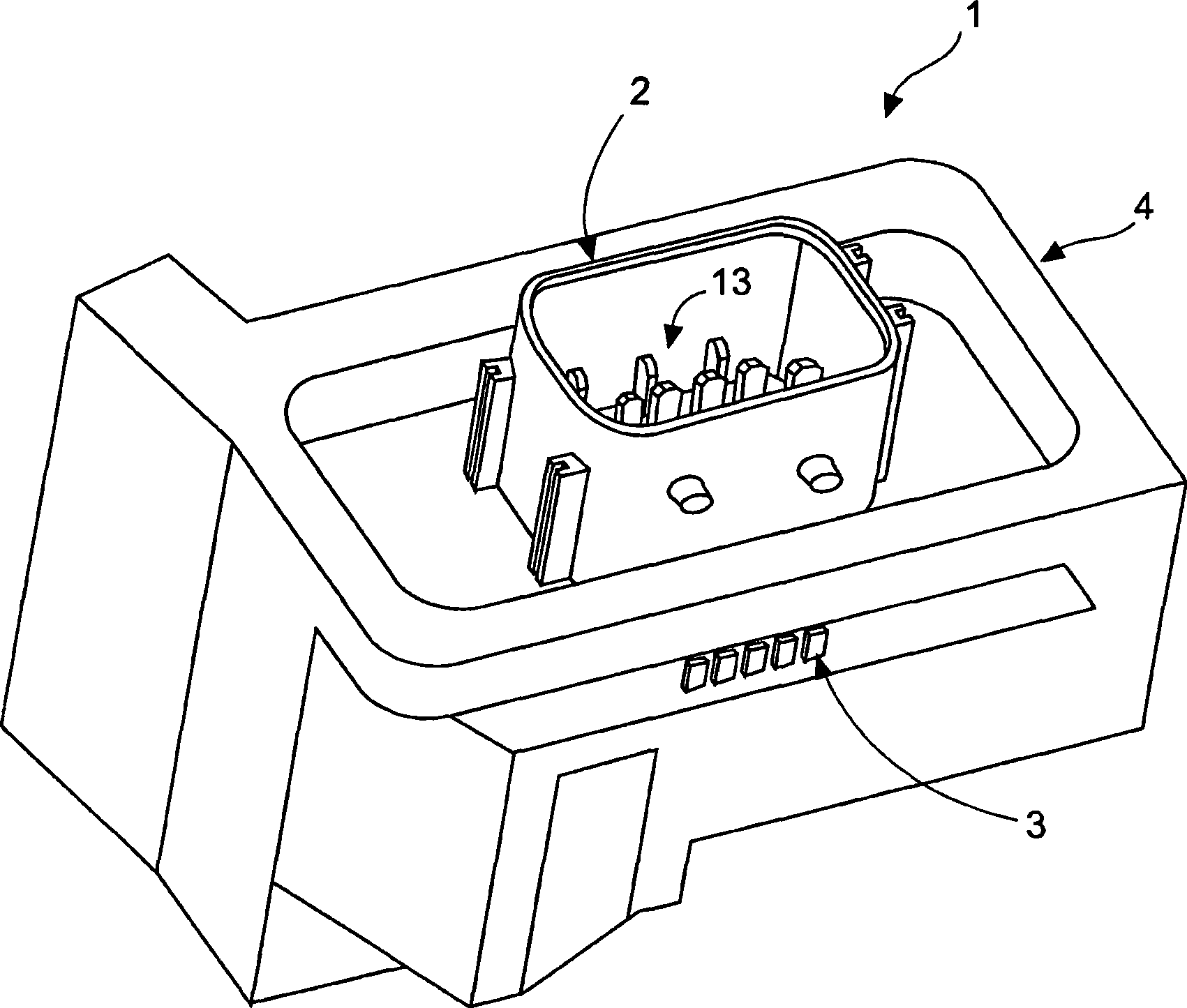
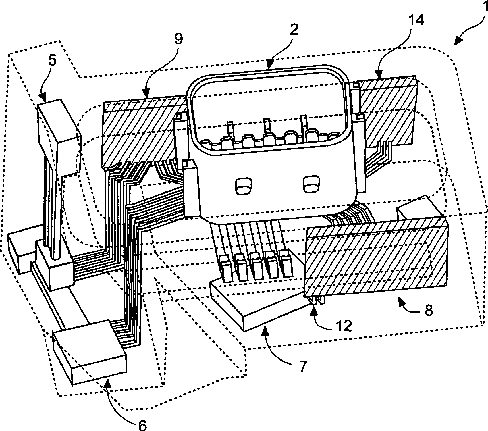
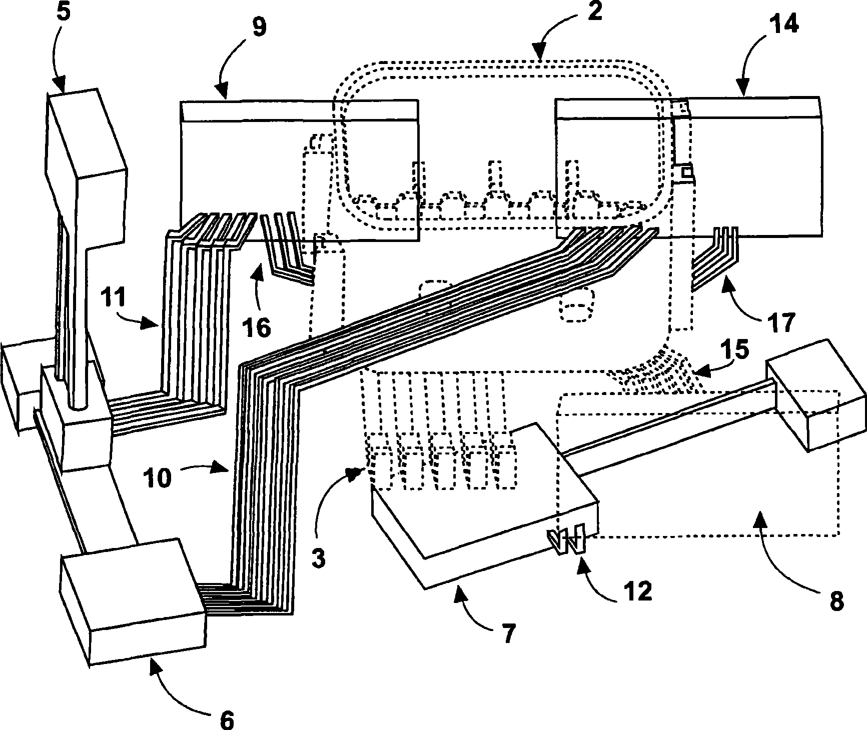
[0019] figure 1 An embodiment of a sensor module according to the invention is shown. A closed housing 4 surrounds the sensor module 1 according to the invention. The first interface 2 and the second interface 3 protrude from the housing. The first interface 2 has an inner metal contact row 13 . These contacts transmit signals of a sensor (not shown) installed in the sensor module 1 and a signal of the second interface 3 to an electronic control unit (Electronic-Control-Unit=ECU, not shown). The second interface 3 also has a row of contacts. Advantageously, the first interface 2 can be embodied as a plug-in connection according to the IP6K9K standard. Of course, other embodiments are also conceivable, as long as the interface can be coupled to the electronic control unit of the gearbox actuator. Therefore, the electronic control unit of the gearbox actuator must have an interface corresponding to the first interface 2 . In an advantageous embodiment, the electronic contr...


PUM


Abstract

The invention relates to an apparatus for connection to a gearbox actuating element of an engine gearbox, having sensors (5, 6, 7) for sensing gearbox shifting positions of a shifting apparatus, and to an interface (2) for transferring the evaluation signals of the sensors (5, 6, 7) to the control electronics of a gearbox actuating element, wherein the sensors (5, 6, 7) are arranged in such a way that their spacing from the interface (2) is smaller than the spacing between the interface (2) and the shifting apparatus which is to be sensed.

Description

technical field [0001] The present invention relates to a device for sensing shift positions of a gearbox, and more particularly to a sensor module for providing sensor signals to a gearbox actuator. Background technique [0002] Electronically controlled transmissions of motor vehicles are adjusted by means of transmission actuators, which receive electronic control signals and convert them into mechanical actuation positions. Here, multiple actuators, usually pneumatically driven actuating pistons, are used for gears, slides, disengagements and sequences. In order to determine the travel position of the actuating piston used for one of the aforementioned functions, a position sensor or travel sensor is used which informs the electronic control unit of the current position of the piston. In this way a control loop is realized which receives a determined gearbox state as a target value and regulates the gearbox as a function of the input signal. [0003] Typical sensors us...

Claims


Application Information

Patent Timeline
Patent Type & Authority Applications(China)
IPC IPC(8): F16H61/00F16H59/70F16H59/04F16H59/10
CPCF16H61/0006F16H59/70B60Y2400/301F16H61/28B60W2420/50Y10T74/20024Y10T74/19251F16H59/04F16H59/10F16H61/00
Inventor 克里斯蒂安·布拉默米可·霍伊里希赖纳·霍尔舍安德里亚斯·西弗斯蒂诺·维格斯
Owner ZF CV SYST EURO BV
Learn More