Method and apparatus for controlling the operational mode of electronic devices in response to sensed conditions

a technology of operational mode and electronic device, applied in the direction of programme control, instruments, high-level techniques, etc., can solve the problem of electric device deactivating power hungry components

Inactive Publication Date: 2005-02-03
QUALCOMM INC
View PDF91 Cites 151 Cited by
  • Summary
  • Abstract
  • Description
  • Claims
  • Application Information

AI Technical Summary

Benefits of technology

An aspect of the invention is to provide a method and / or apparatus that controls an electrical device by sensing when a user would like to switch to a desired mode of operation of the electrical device and to switch the modes of the device in response thereto. An aspect of the invention is to activate and / or deactive components or to switch between modes of an electrical device in response to a variety of events and / or conditions, such as change in position of the device, distance of the device to or from a target object or target position, visual events or repetitive events, for example. Alternate embodiments of the invention might observe different types of condition, such as rate of acceleration or change in rate of acceleration of the device. Embodiments of the present invention can progressively activate components of the electrical device as it becomes more and more likely that the components are going to be needed by the electrical device. In particular, if it appears based upon sensed conditions that the electrical device is going to go into a desired mode and that particular components of the electrical device are going to be needed in the desired mode, the embodiment of the invention can activate individual components of the electrical device at different points in time as it becomes more and more likely that the components will be needed. This progressive activation could be staged in such a way that as more indications are sensed that the particular components are going to be needed (e.g. indications of user intent to put the electronic device into a particular mode are sensed), then the resources dedicated to the desired mode, for example, will be increased. Similarly, embodiments of the present invention could allow progressive deactivation of components of the electrical device as it becomes less and less likely that the components will be needed.

Problems solved by technology

The method and / or apparatus can also cause the electrical device to de-activate power hungry components when they are not needed.

Method used


Image

  • Method and apparatus for controlling the operational mode of electronic devices in response to sensed conditions
  • Method and apparatus for controlling the operational mode of electronic devices in response to sensed conditions
  • Method and apparatus for controlling the operational mode of electronic devices in response to sensed conditions

Examples


first embodiment

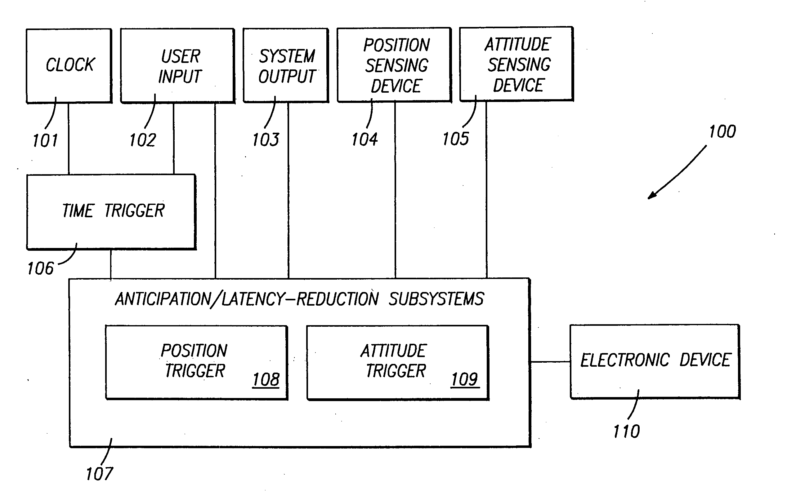
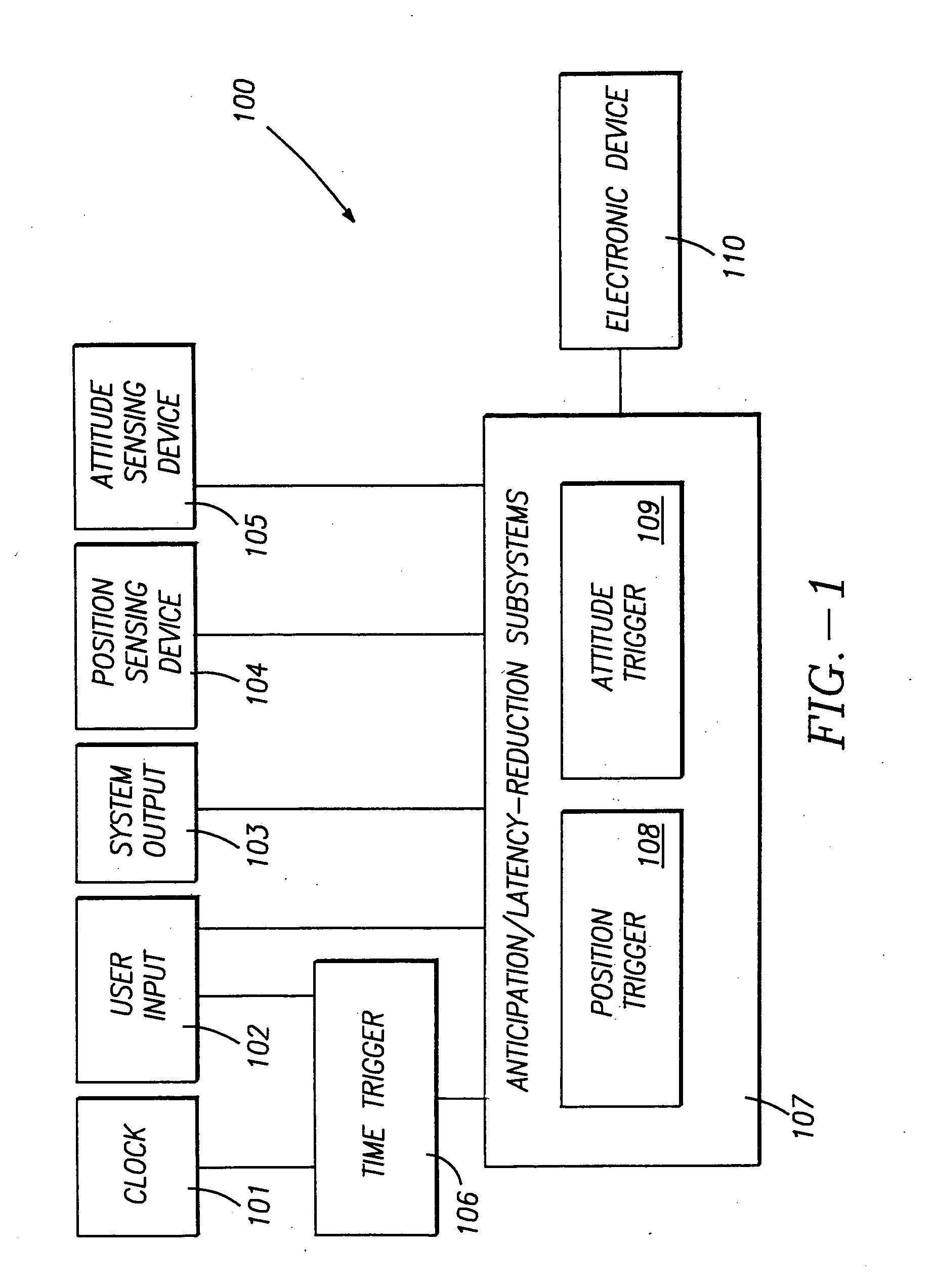
FIG. 1 illustrates a block diagram of system 100 which is the invention. This system 100 is a device usage detection system that monitors the physical characteristics of an electronic device 110 or monitors other predefined conditions in order to activate or otherwise control the electronic device 110. System 100 activates or controls device 110 when the system detects indications of intent to use or other predefined conditions. System 100 comprises a clock 101, a user input 102, a system output 103, a position sensing device 104, an attitude sensing device 105, a time trigger 106, and an anticipation / latency-reduction subsystem 107. The clock 101, the time trigger 106, and the anticipation / latency reduction subsystem 107 form a control subsystem. Alternate embodiments are not limited to this particular control system or to control systems that have structure equivalent to this particular control system. The user input 102 can be any form of input mechanism including without limitat...

second embodiment

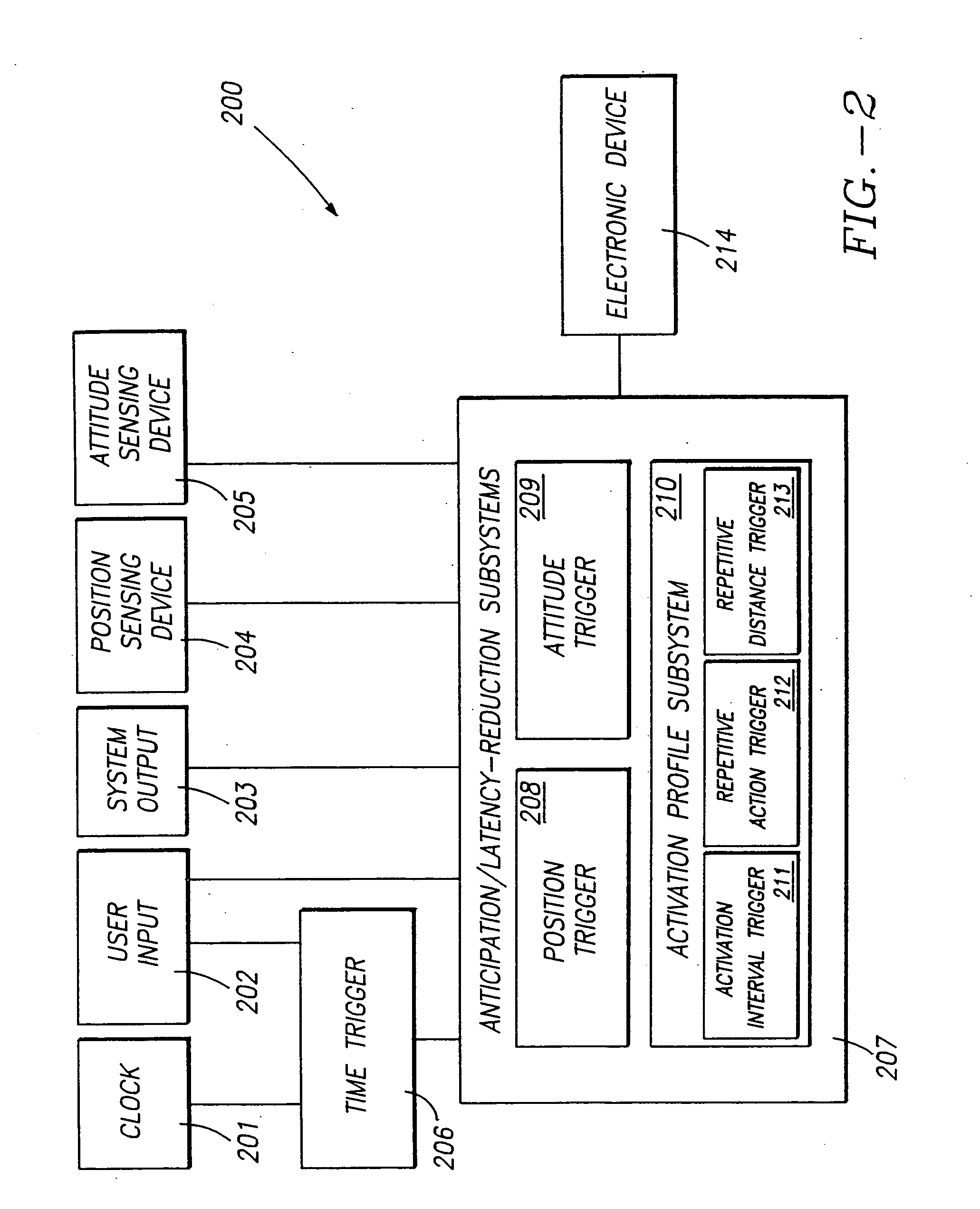
FIG. 2 is a block diagram of a system 200 that is the invention. The system 200 includes components that operate in the same manner as those described with respect to the system 100. The similar components are numbered similarly (e.g. time trigger 206 operates in the same manner as time trigger 106). In addition to having such similar components, system 200 includes an activation profile subsystem 210. This subsystem 210 is included as part of the anticipation / latency-reduction subsystem 207 of system 200.

Subsystem 210 is designed to allow the system 200 to recognize, over a period of use, repetitive actions taken by a user or other repetitive conditions that occur prior to activation of device 110. Based upon this recognition, the subsystem 210 develops specific activation profiles that are associated with particular repetitive actions or particular repetitive conditions. These activation profiles allow the system 200 to recognize the particular repetitive actions or conditions as...


PUM


Abstract

A system is disclosed that senses physical characteristics of an electronic device. The system controls the electronic device in response to the sensed physical characteristics. The system includes a control subsystem. The control subsystem includes a time trigger and an anticipation / latency reduction subsystem. The anticipation / latency reduction subsystem includes additional subsystems such as a time trigger, a position trigger and an attitude trigger. In an alternate embodiment, the anticipation / latency reduction subsystem also includes an activation interval trigger, a repetitive action trigger and a repetitive distance trigger. The various triggers can be implemented using processors that execute software. The system also includes sensing devices, such as a position sensing device and an attitude sensing device, to sense physical characteristics of the particular electronic device being controlled. The control subsystem receives signals from the sensing devices. Physical characteristic information obtained from these signals is provided to the various triggers. In response to this physical characteristic information, the various triggers process the physical characteristic information such that the system controls the electronic device.

Description

FIELD OF THE INVENTION The present invention relates to methods and apparatus for improving the performance of electrical devices, and more particularly to methods and apparatus that sense a variety of conditions and that control electrical devices in response to the conditions sensed. BACKGROUND Electronic devices are typically designed to perform specific functions. From the moment an electronic device is turned on, it may be fully functional to perform its designed task. This approach may be fine for simple devices. This approach, however, may present disadvantages in complex systems. For example, a complex system may consume relatively large amounts of power. If the complex system is fully functional at all times, power consumption typically remains high even when the system is not actually being used. This relatively high power consumption can be a particularly important concern for battery-powered systems where high power consumption can cause a short operational life. Anot...

Claims


Application Information

Patent Timeline
Patent Type & Authority Applications(United States)
IPC IPC(8): G05B19/042G06F1/32
CPCG06F1/3287G06F1/3203G06F1/3215Y02B60/1282Y02B60/32G05B2219/25291G06F1/3209G05B19/042Y02B60/1278Y02D10/00Y02D30/50
Inventor ELLENBY, JOHNELLENBY, PETER MALCOLMELLENBY, THOMAS WILLIAM
Owner QUALCOMM INC
Why Eureka
Try Eureka