
Method and apparatus for controlling user interface of electronic device using virtual plane

Active Publication Date: 2008-05-22
SAMSUNG ELECTRONICS CO LTD
View PDF16 Cites 146 Cited by
  • Summary
  • Abstract
  • Description
  • Claims
  • Application Information

AI Technical Summary

Benefits of technology

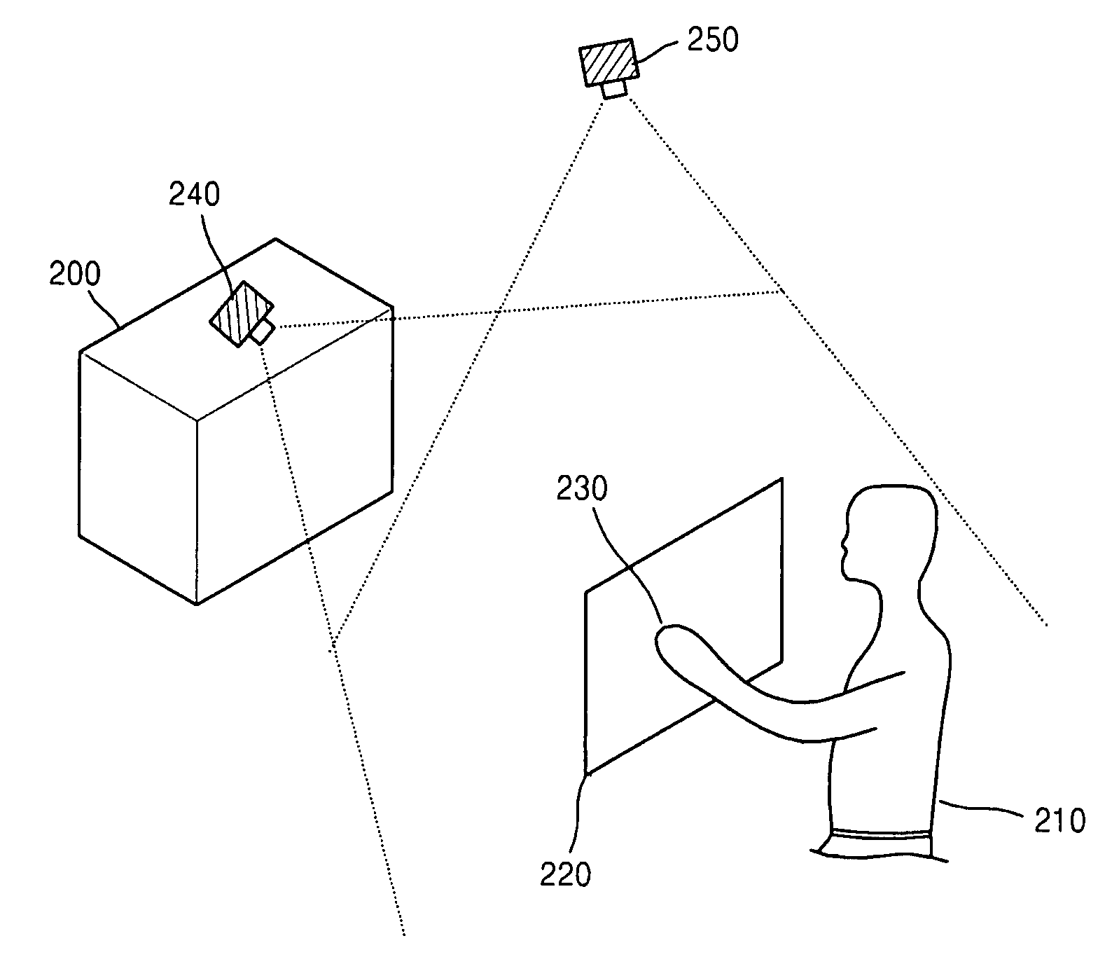
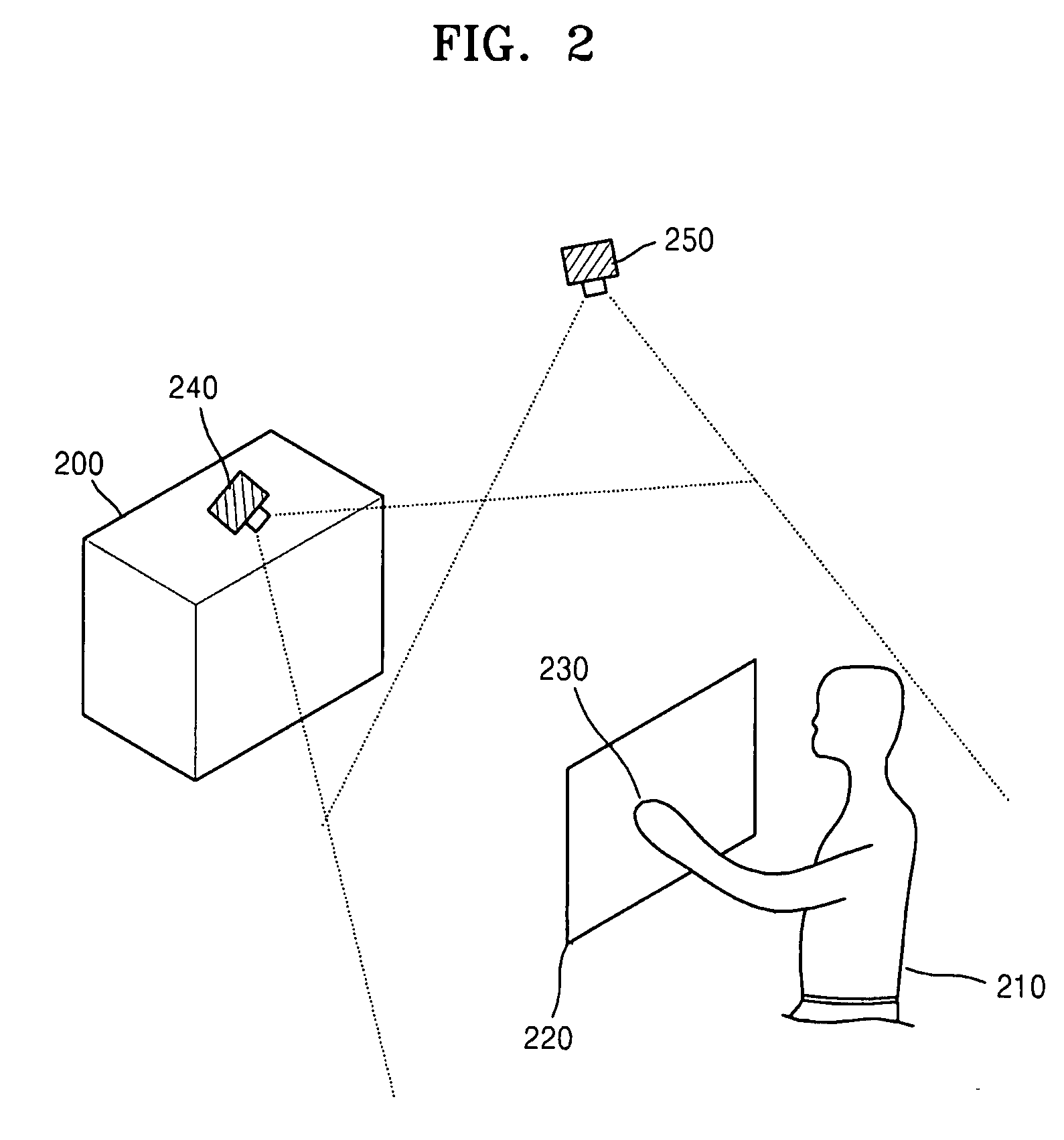
[0012]In the method and apparatus for controlling a UI of an electronic device by using a virtual plane, the virtual plane is initialized according to spatial coordinates of two or more images detected by using locations of the images displayed in an image display unit of a first image capture device and an image display unit of a second image capture device. Furthermore, the location of a marker is determined and is indicated by a specific image on the virtual plane. Furthermore, a screen pointer corresponding to the marker is displayed at a position where the marker is located in an image display unit corresponding to the virtual plane. Furthermore, a menu of the electronic device is selected which is pointed to by the screen pointer while moving the marker. Accordingly, a user can initialize the virtual plane by performing a simple operation such as making a gesture or changing eye positions. Therefore, there is an advantage in that the UI of the electronic device can be conveniently controlled by performing a simple operation by using the virtual plane created regardless of a user's location.

Problems solved by technology

However, as electronic devices have become more complex than before, the number of buttons of the remote controls has consequently increased in order to control the electronic devices.
Thus, it is not easy to remember all the functions assigned to the respective buttons.
Moreover, with the increase in functions of desktop video (DTV), a controller for controlling these functions requires more space.
That is, there is a problem in that a radius of action of the user is restricted.
Furthermore, in this method, since a user's hand is detected according to skin color, the detection cannot be properly made when illumination around the user changes.
Furthermore, since different actions of the user are assigned to operations of the electronic device, the user has to remember a lot of actions, which is inconvenient.
However, this method still causes inconvenience in terms of installing the image capture devices since three image capture devices have to be installed at a fixed location such as on the wall or ceiling.
Moreover, there has been a difficulty in controlling screen icons because even an insignificant motion of a finger results in a large motion on a screen of the electronic device.
In addition, there is another disadvantage in that the electronic device can only be used in a fixed location.

Method used


Image

  • Method and apparatus for controlling user interface of electronic device using virtual plane
  • Method and apparatus for controlling user interface of electronic device using virtual plane
  • Method and apparatus for controlling user interface of electronic device using virtual plane

Examples


Embodiment Construction

[0046]The present invention may, be embodied in many different forms and should not be construed as being limited to the aforementioned aspects set forth herein. The following aspects of the present invention are provided so that this disclosure will be thorough and complete, and will fully convey the concept of the invention to those skilled in the art.

[0047]Hereinafter, exemplary embodiments of the present invention will be described in detail with reference to the accompanying drawings.

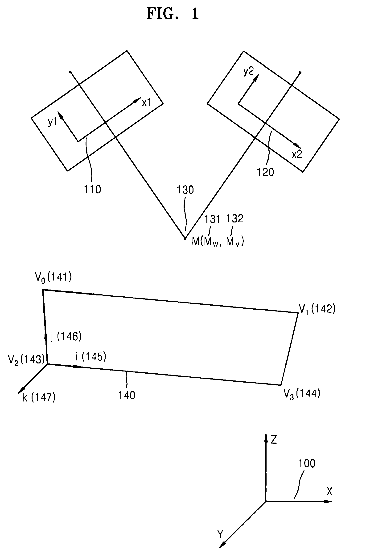
[0048]FIG. 1 illustrates main elements and their geometric relationships according to an embodiment of the present invention. 100(X, Y, Z) is represented in a world coordinate system. The world coordinate system is used when a location of a figure is designated by an application program for computer graphics (CG). The world coordinate system is irrelevant to a device. That is, the world coordinate system is a device-independent Cartesian coordinate system. The location of a specific image existing ...


PUM


Abstract

Provided is a method and apparatus for controlling a user interface (UI) of an electronic device by using a specific region of a virtual plane. In the method, the virtual plane is initialized according to spatial coordinates of two or more images detected by using locations of the images displayed in an image display unit of a first image capture device and an image display unit of a second image capture device. Furthermore, the location of a marker is determined and is indicated by a specific image on the virtual plane. Furthermore, a screen pointer corresponding to the marker is displayed at a position where the marker is located in an image display unit corresponding to the virtual plane. Furthermore, a menu of the electronic device is selected which is pointed to by the screen pointer while moving the marker. Accordingly, a user can conveniently control the UI of the electronic device by performing a simple operation.

Description

CROSS-REFERENCE TO RELATED PATENT APPLICATION[0001]This application claims the benefit of Korean Patent Application No. 10-2006-0114716, filed on Nov. 20, 2006, in the Korean Intellectual Property Office, the disclosure of which is incorporated herein in its entirety by reference.BACKGROUND OF THE INVENTION[0002]1. Field of the Invention[0003]The present invention relates to human computer interaction (HCI) such as computer vision, pattern recognition, and gesture recognition, and more particularly, to an apparatus and method for easily controlling a user interface (UI) of an electronic device by using a virtual plane.[0004]2. Description of the Related Art[0005]Remote controls have been conventionally used to control electronic devices such as television sets (TVs). Remote controls facilitate control of the electronic devices. However, as electronic devices have become more complex than before, the number of buttons of the remote controls has consequently increased in order to cont...

Claims


Application Information

Patent Timeline
IPC IPC(8): G06F3/033
CPCG06F3/0325G06F3/017G06F3/0481G06F3/0482G06F3/0484
Inventor MA, GENGYUMOON, YOUNG-SUYOO, YONG-SEOK
Owner SAMSUNG ELECTRONICS CO LTD
Learn More