Input having concentric touch pads

a technology of input device and touch pad, which is applied in the direction of electric digital data processing, instruments, computing, etc., can solve the problems of not fully utilizing all digits of users, physical input controls are not adaptable to different types of applications, and affect the number of user actions processed by the input devi

Inactive Publication Date: 2007-03-15
IBM CORP
View PDF4 Cites 144 Cited by
  • Summary
  • Abstract
  • Description
  • Claims
  • Application Information

AI Technical Summary

Benefits of technology

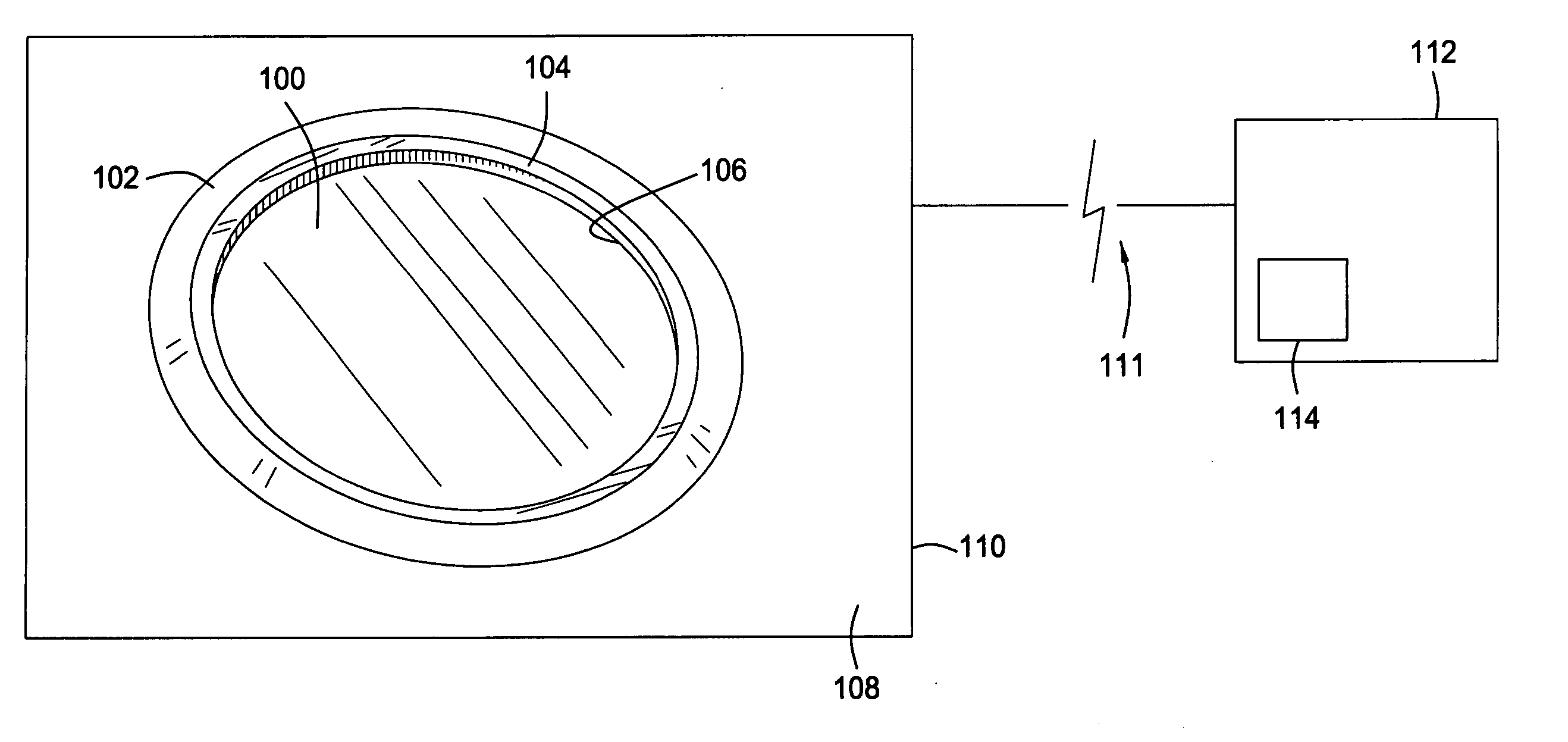
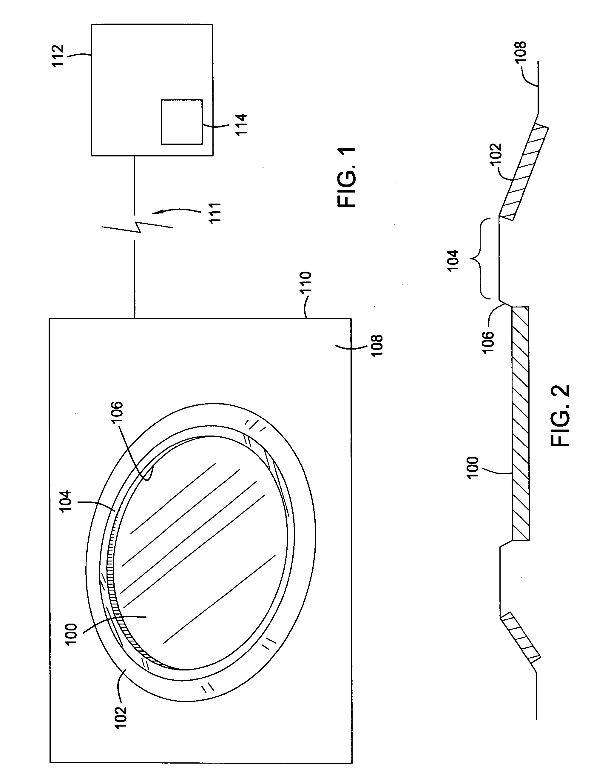
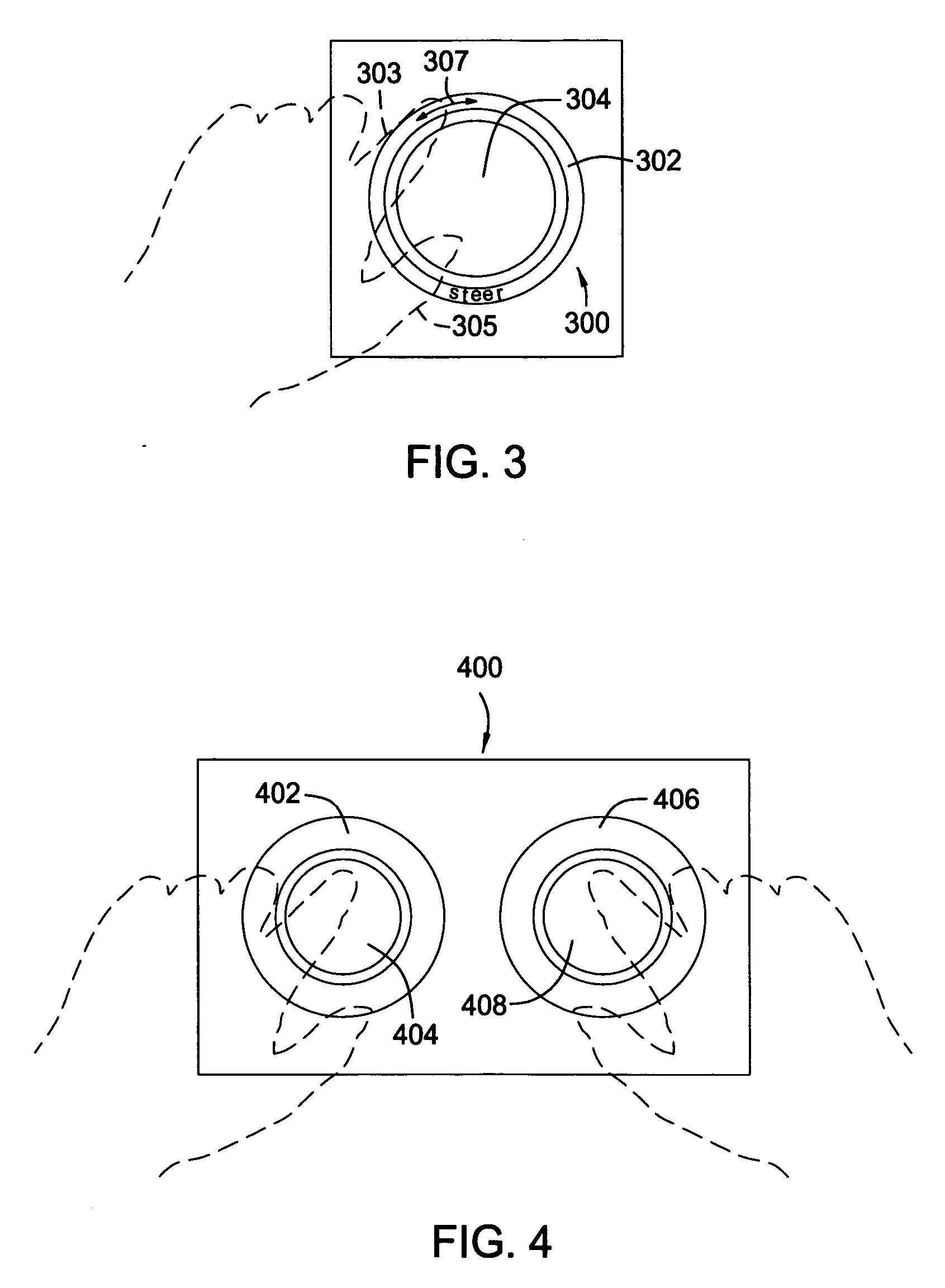
[0010] In one embodiment, an input device for generating commands to control an electronic device includes a center touch pad defining a substantially circular shape and an outer touch pad generally concentric with the center touch pad. Thus, the outer touch pad defines a ring shape. Further, an inactive surface at least partially surrounds the center touch pad and physically separates the center touch pad from the outer touch pad.
[0011] In another embodiment, a method of generating commands to control an electronic device includes providing an input device in communication with the electronic device. The input device includes a center touch pad, an annular touch pad disposed concentrically around the center touch pad, and an inactive surface disposed between the center touch pad and the annular touch pad. Receiving input corresponding to contact on the center touch pad with a first rotational sliding motion provides a first input signal to the electronic device to adjust a first function of the electronic device based on direction of the first rotational sliding motion. Similarly, receiving input corresponding to contacting on the annular touch pad with a second rotational sliding motion provides a second input signal to the electronic device to adjust a second function of the electronic device based on di

Problems solved by technology

One issue regarding the input device involves its design.
Moreover, the design can affect the number of user actions processed by the input device.
For example, designs of the mouse and prior touch pads are for use with a single hand of the user and do not fully utilize all digits of the user.
However, the physical input controls are not adaptable for different types of applications that may be required with the electronic device.
For example, buttons and switches that are mechanical in nature provide limited control with regards to making selections since the se

Method used


Image

  • Input having concentric touch pads
  • Input having concentric touch pads
  • Input having concentric touch pads

Examples


Embodiment Construction

[0026] In the following, reference is made to embodiments of the invention. However, it should be understood that the invention is not limited to specific described embodiments. Instead, any combination of the following features and elements, whether related to different embodiments or not, is contemplated to implement and practice the invention. Furthermore, in various embodiments the invention provides numerous advantages over the prior art. However, although embodiments of the invention may achieve advantages over other possible solutions and / or over the prior art, whether or not a particular advantage is achieved by a given embodiment is not limiting of the invention. Thus, the following aspects, features, embodiments and advantages are merely illustrative and are not considered elements or limitations of the appended claims except where explicitly recited in a claim(s). Likewise, reference to “the invention” shall not be construed as a generalization of any inventive subject ma...


PUM


Abstract

Methods and apparatus include an input device for controlling an electronic device. The input device includes concentric touch pads. Contact with the touch pads includes tapping and/or sliding movement in order to provide signals that are processed and sent to the electronic device, which performs operations based on these inputs.

Description

BACKGROUND OF THE INVENTION [0001] 1. Field of the Invention [0002] The invention generally relates to an electronic input device having touch pads. [0003] 2. Description of the Related Art [0004] Many styles of input devices exist that enable a user to perform operations in an electronic device. For example, the input devices can include a mouse, touch pads, trackballs, buttons, switches, joysticks, slider bars and rotating or jog dials. These input devices are operated by the user to control the electronic device such as a computer, a video game, a phone, a remote control, a portable audio / video device and disc jockey equipment. [0005] One issue regarding the input device involves its design. The design of the input device is critical for effectively controlling numerous functions of the electronic devices and navigating increasingly complex operations and graphical displays. Accordingly, the design of the input device must be easy to use, comfortable for the user, and facilitate ...

Claims


Application Information

Patent Timeline
IPC IPC(8): G09G5/00
CPCG06F3/03547
Inventor SCHULTZ, KEVIN L.TIERNEY, KELLY J.
Owner IBM CORP
Why Eureka
Try Eureka