
Image forming method, image forming apparatus and toner image pattern

a technology of image forming and toner image, which is applied in the direction of electrographic process apparatus, instruments, printing, etc., can solve the problems of color registration error, effect of errors, and appearance conspicuous

Inactive Publication Date: 2008-09-04
RICOH KK
View PDF5 Cites 27 Cited by
  • Summary
  • Abstract
  • Description
  • Claims
  • Application Information

AI Technical Summary

Benefits of technology

[0008]Accordingly, it is a general object of the present invention to provide a novel and useful image forming method, image forming apparatus and toner image pattern, in which the problems described above are minimized.
[0009]Another and more specific object of the present invention is to provide an image forming method, an image forming apparatus and a toner image pattern, which can prevent an overlap of toner images for correction, of different colors, that would otherwise make it impossible to detect the toner images for correction in a normal manner.

Problems solved by technology

For this reason, a color registration error may occur if an error is generated in relative positions of the 4 color toner images.
However, because the toner images tmnY, tmnC, tmnK and tmnM for correction are arranged at both ends of the transfer belt along the main scan direction, the effects of errors, such as an error in an optical system of the exposure unit, appear conspicuously in terms of the positions where the toner images tmnY, tmnC, tmnK and tmnM are formed.

Method used


Image

  • Image forming method, image forming apparatus and toner image pattern
  • Image forming method, image forming apparatus and toner image pattern
  • Image forming method, image forming apparatus and toner image pattern

Examples


Embodiment Construction

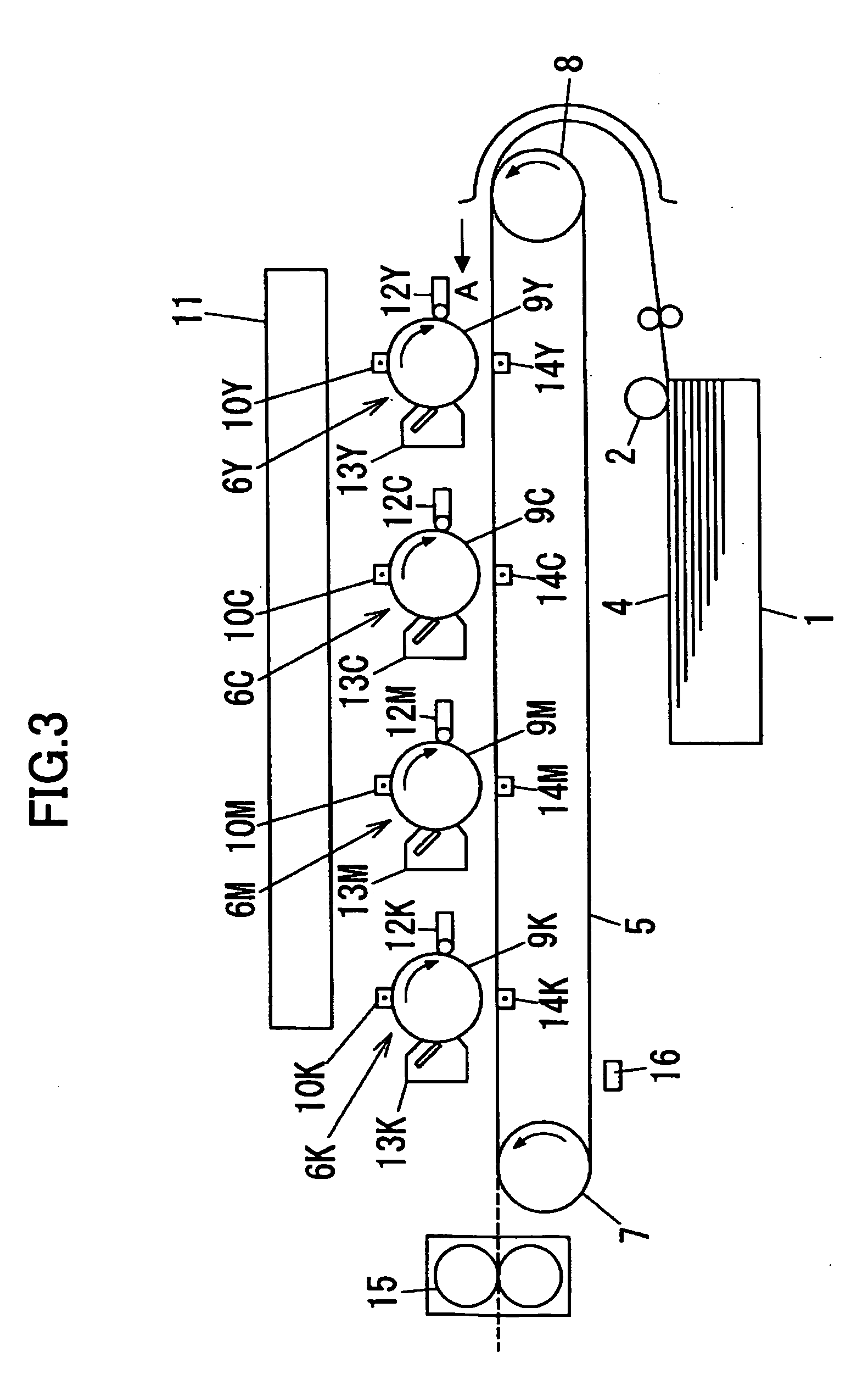
[0023]A description will be given of embodiments of an image forming method, an image forming apparatus and a toner image pattern according to the present invention, by referring to FIG. 3 and the subsequent figures.

[0024]In the embodiment described hereunder, the present invention is applied to a tandem type color laser printer. However, as is evident to those skilled in the art, the application of the present invention is not limited to the color laser printer, and the present invention is similarly applicable to image forming apparatuses in general which employ an electrophotography technique, such as color copying machines and facsimile machines.

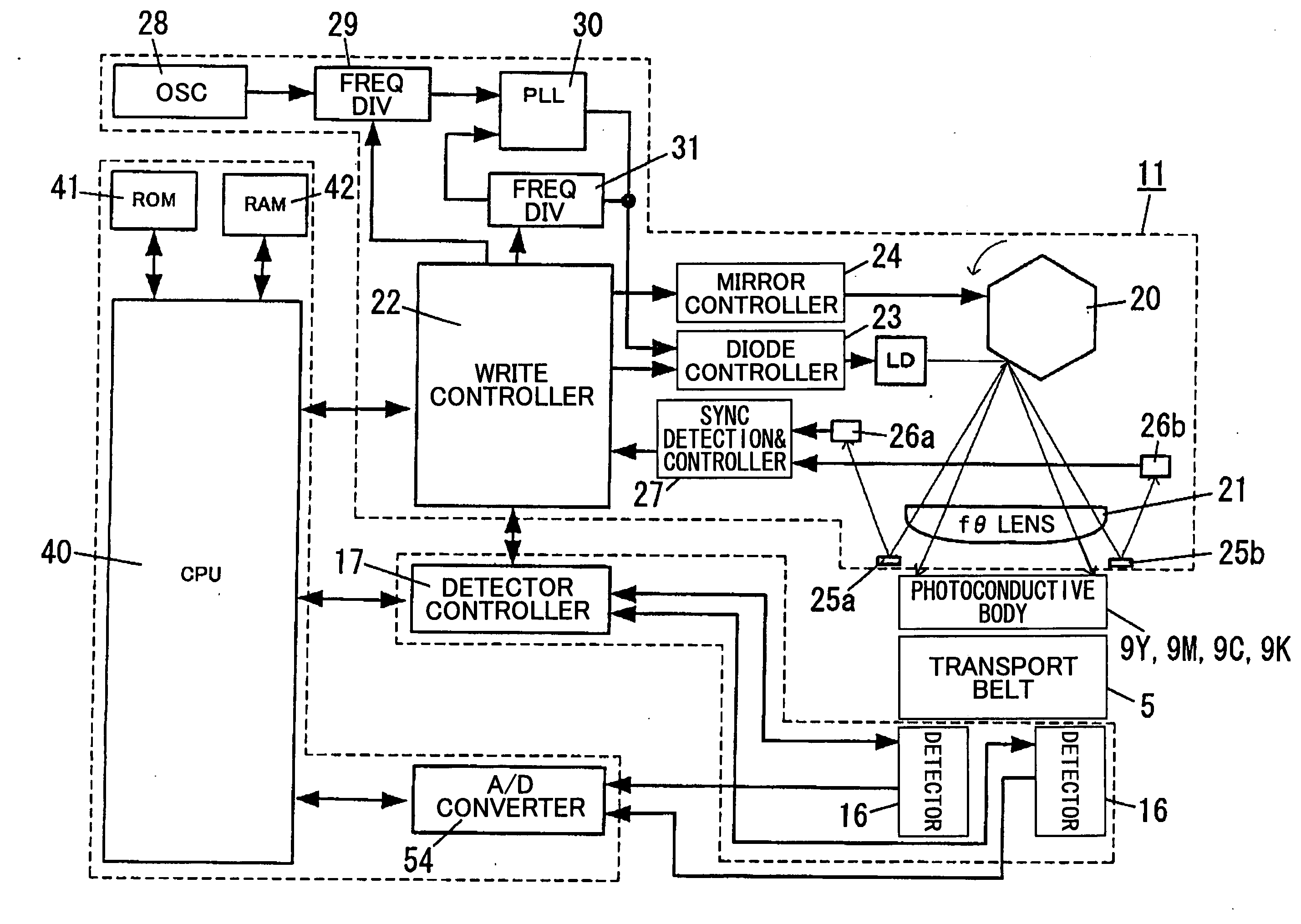
[0025]FIG. 3 is a schematic diagram showing a general structure of a part of the image forming apparatus in an embodiment of the present invention, and FIG. 4 is a system block diagram showing a part of the image forming apparatus.

[0026]In FIG. 3, first, second, third and fourth image processing parts 6Y, 6C, 6M and 6K, respectively for ...


PUM


Abstract

An image forming method exposes image bearing members by simultaneously reflecting light beams corresponding to different colors by different reflection surfaces of a polygon mirror, transforms electrostatic latent images formed on the image bearing members into toner images for correction, transfers the toner images in an overlapping manner onto a transfer body, and calibrates overlapping positions of the toner images based on an optical detection of the toner images. The toner images are arranged at positions on the transfer body such that the toner images of different colors have no overlap therebetween, even if the toner images shift in a direction perpendicular to the transport direction due to a color registration error. Two first toner images simultaneously formed by two corresponding light beams reflected by one reflection surface of the polygon mirror are arranged adjacent to each other in a transport direction of the transfer body, and are sandwiched by two second toner images simultaneously formed by the two corresponding light beams reflected by the one reflection surface of the polygon mirror along the transport direction.

Description

BACKGROUND OF THE INVENTION[0001]1. Field of the Invention[0002]The present invention generally relates to image forming methods, image forming apparatuses and toner image patterns, and more particularly to an image forming method for calibrating a color registration error caused by a positional error of a plurality of color toner images that are formed on a transfer body, an image forming apparatus which employs such an image forming method, and a toner image pattern suited for use by such an image forming method.[0003]2. Description of the Related Art[0004]Image forming apparatuses typified by color copying machines and color laser printers include tandem type image forming apparatuses. In one example of the tandem type image forming apparatus, 4 color toner images of yellow, cyan, magenta and black are successively transferred from respective photoconductive bodies onto a transfer body, such as a transfer belt or a transfer sheet or medium (for example, paper). For this reason, a...

Claims


Application Information

Patent Timeline
IPC IPC(8): G03G15/01
CPCG03G15/011G03G2215/0161G03G2215/0141
Inventor MIYADERA, TATSUYA
Owner RICOH KK
Learn More