Conveyor guard

a conveyor and guard technology, applied in the field of guards, can solve the problems of affecting affecting the safety of the luggage, so as to improve the usability and reliability of the prior art devi

Active Publication Date: 2009-05-12
VESTERGAARD MARTIN
View PDF16 Cites 65 Cited by
  • Summary
  • Abstract
  • Description
  • Claims
  • Application Information

AI Technical Summary

Benefits of technology

[0010]Consequently, it is an object of the present invention to alleviate the disadvantages mentioned above, and improve the usability and reliability of the prior art devices.DESCRIPTION OF THE INVENTION
[0012]As objects are transported on the conveying structure, straps, tags and the like which otherwise would have a tendency to fall down between two adjacent conveying elements will be supported by the guard connected between the extremities of the conveying elements such that they will be kept substantially free from the conveying elements, and will not be able to become entangled for example by encircling the end of the conveying element, become stuck between two conveying elements which are in close proximity, and the like. Furthermore, the guard may be dimensioned such that it will help delimit the side-flexing abilities of the conveying structure, whereby it is assured that two adjacent conveying elements do not come into contact, and furthermore that two adjacent conveying elements do not come substantially out of a common transport plane which could interfere and jeopardise with the proper working of the entire conveyor structure.
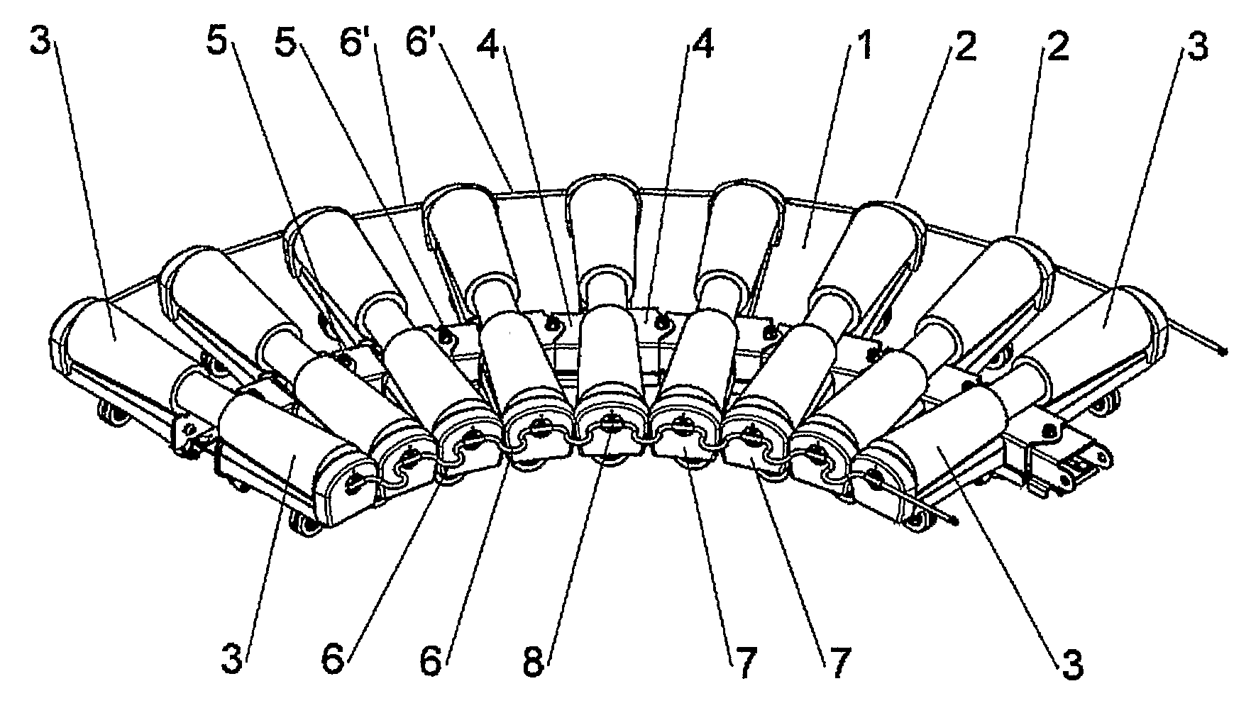
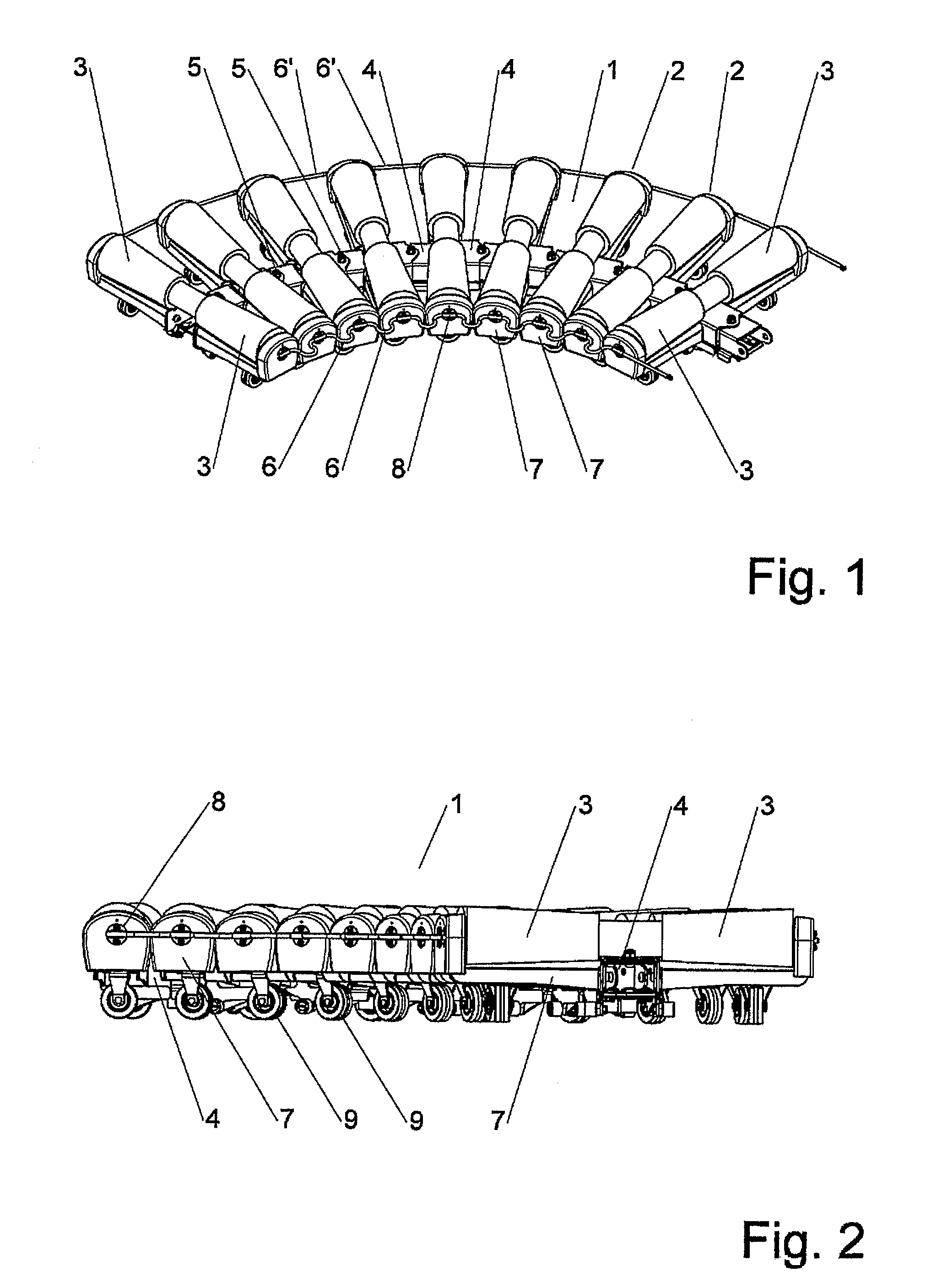
[0013]In a further advantageous embodiment, the conveying elements are rollers, and the guard is fastened between non-rotating parts of each roller. As mentioned above in relation to the prior art, some of the conveying structures to which the present invention is directed, comprise interconnected conveying elements in the shape of rollers. For these rollers, it is advantageous to attach the guard to a non-rotating part at the very extreme end of the conveying elements such that it is assured that the guard does not interfere with the conveying element as such.
[0015]Although it is contemplated that the conveying elements may extend to one side only in relation to the articulated joint provided between two adjacent conveying elements, it is also contemplated that the conveying elements may extend on either side of the articulated joint, and that guards are provided on both extremities of each conveying element. In this configuration, a further advantage is provided with the guard according to the present invention. By dimensioning the length of the guard appropriately, it is possible to assure that as the conveying structure flexes to one side or the other, the guards arranged along one extremity of the conveying elements will be fully extended in a situation where the conveying elements along the opposing side are just not touching. In this way, the guard will act as a further security in assuring that the side-flexing capabilities of the conveying structure per se are not over-extended such that adjacent conveying elements will interfere with each other.
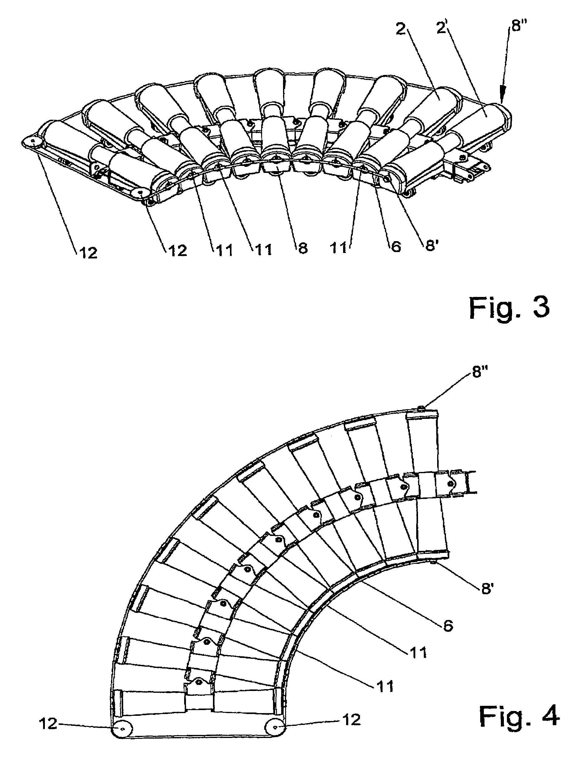
[0017]In a further advantageous embodiment, the guard is extendable / retractable, for example by a telescopic construction such that it may alter length depending on the distance between the extremities of two adjacent conveying elements. The configuration of the guard being extendable / retractable, such as it may be achieved with a telescopic construction, which for example is made of a hard plastic material or steel, provides added rigidity and stiffness to the conveying structure. By arranging the fastening means of the guard to the extremities of the conveying elements in a proper way, fully articulated joints may be provided such that the flexibility of the conveying structure is not hampered. The more rigid guard members according to this embodiment in comparison to the more flexible and / or resilient guards provided in the embodiment mentioned above, may add further stiffness to the conveyor structure such that the problems relating to one or more conveying elements coming out of the transport plane in a scissor-like movement may be further minimized.
[0019]In this fashion, the guard member having a fixed length is fastened to the same conveying element. By treading the guard through eye parts on the extremities of the remaining conveying elements, and turning the guard around pulleys at the opposite end of the conveyor, and furthermore guiding the guard through eye parts arranged at the opposite extremities of the conveying elements back to the first element, and fastening the guard to this element, one continuous guard member is provided. As the conveyor flexes to one side, the eye parts will slide along the guard such that the extremities on the inside of the turn will have a lesser spacing, and the eye parts on outside of the turn will have a larger spacing. The pulleys arranged at the end allows for easy manoeuvring, and adaptation of the conveying structure such that the guard is not a hindrance for the flexibility of the conveying structure.

Problems solved by technology

In particular for luggage and the like, the luggage labels are very fragile, and may easily become detached from the piece of luggage.
This may lead to problems relating to which destination to forward the luggage to, which aircraft it was meant for, who it belongs to, etc.
If this information is lost, the overall level of recognizability and determinability of the objects or produce used in the production process becomes unstable and unreliable.
Furthermore, common for all these devices is the fact that as they are used in a side-flexing manner, there will be a varying gap between the conveying elements along the inner side of the curve in comparison to the outer side of the curve.
Furthermore, as this type of conveying structure is not provided with guiding elements along the extremities, it may have a tendency to twist in the plane such that one conveying element may be seriously out of the conveying plane due to the tensions arising in the system as the conveying structure is made to side-flex.

Method used


Image

  • Conveyor guard
  • Conveyor guard
  • Conveyor guard

Examples


second embodiment

[0024]FIGS. 3 and 4 illustrate the guard configuration,

third embodiment

[0025]FIG. 5 illustrates a guard arrangement.

DETAILED DESCRIPTION OF THE INVENTION

[0026]FIG. 1 illustrates a double-sided conveyor structure having guards on both extremities FIG. 2 illustrates another view of this conveyor structure.

[0027]The conveyor structure 1 comprises a number of conveying elements 2 which are interconnected by articulated joints 5 such that one conveying element 2 may flex in relation to an adjacent conveying element 2.

[0028]In this embodiment, the conveying elements 2 comprise rollers 3 which are arranged on brackets 7. The advantages of this embodiment are further developed in the above mentioned prior patent application from the same applicant.

[0029]The brackets 7 are equipped with wheels 9 such that the entire conveyor structure 1 easily may be manoeuvred on a surface. The rollers 3 are attached through central chain box members 4 which articulate via the joints 5 in relation to adjacent chain box elements 4.

[0030]The guards 6 are provided along both ext...


PUM


Abstract

A guard for a conveyor used for conveying objects where the objects may have elements which extend outside the object itself, and which thereby may become stuck in the conveyor structure per se is provided between extremities of the free ends of conveying elements to prevent entanglement.

Description

[0001]This application claims the benefit of Danish Application No. PA200500044 filed Jan. 11, 2005 and PCT / DK2006 / 000017 filed Jan. 11, 2006, which are hereby incorporated by reference in their entirety.FIELD OF THE INVENTION[0002]The present invention relates to a guard for use with a conveyor structure.BACKGROUND OF THE INVENTION[0003]Conveyors are used in industries for a number of purposes, and the present invention is particularly directed to a conveyor used for conveying objects where the objects may have elements or parts which extend outside the object itself, and which thereby may become stuck or entangled in the conveyor structure per se.[0004]Such objects may be labels, handles, straps, etc. of luggage to be conveyed to and from for example the cargo bay in aircrafts, or be straps, strings or wires of products being conveyed in a manufacturing process.[0005]The objects which have these elements extending from the object itself may be partly or wholly destroyed and furthe...

Claims


Application Information

Patent Timeline
Patent Type & Authority Patents(United States)
IPC IPC(8): B65G15/02
CPCB65G13/12
Inventor VESTERGAARD, MARTIN
Owner VESTERGAARD MARTIN
Why Eureka
Try Eureka