Method of moulding

a moulding and technology of conductive inks, applied in the field of moulding, can solve the problems of brittleness of the layer formed from such conductive inks, difficulty in integrating touch sensitive technology into the moulded article, and difficulty in integrating known touch sensitive elements and lighting into the film structure, so as to achieve more attractive and/or user-friendly electronic interfaces and improve manufacturing efficiency. the effect of cost effectiveness

Inactive Publication Date: 2014-02-06
FISCHER TECH
View PDF4 Cites 60 Cited by
  • Summary
  • Abstract
  • Description
  • Claims
  • Application Information

AI Technical Summary

Benefits of technology

[0007]In general terms in a first aspect the invention proposes to minimise the problem of cracking in the conductive tracks in contoured sensing zones

Problems solved by technology

It will be appreciated however that, while advantages can be gained by the use of touch sensitive controls on computer screens and flat panel input areas, certain limitations exist for integrating touch sensitive technology into moulded articles.
Haag avoids spanning the inks within the sensing zones and does not propose to substantially solve problems associated with cracking and the like in those zones.
Still further, while capacitive switches and lighting mat

Method used


Image

  • Method of moulding
  • Method of moulding
  • Method of moulding

Examples


Embodiment Construction

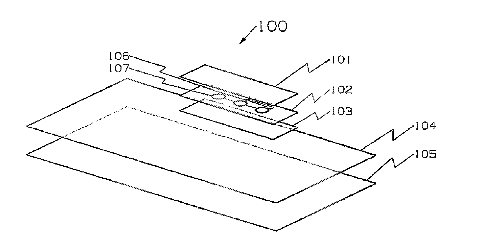
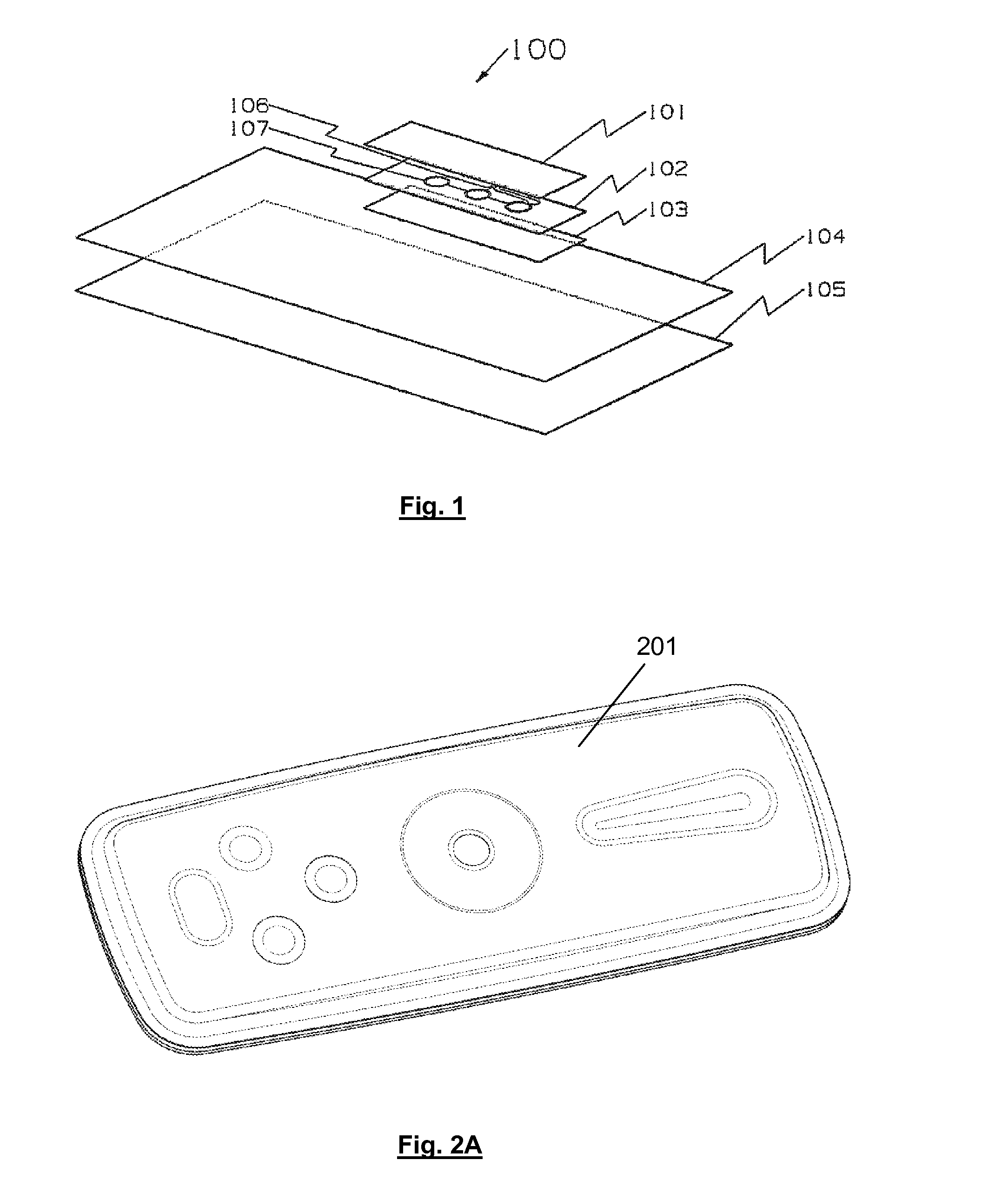
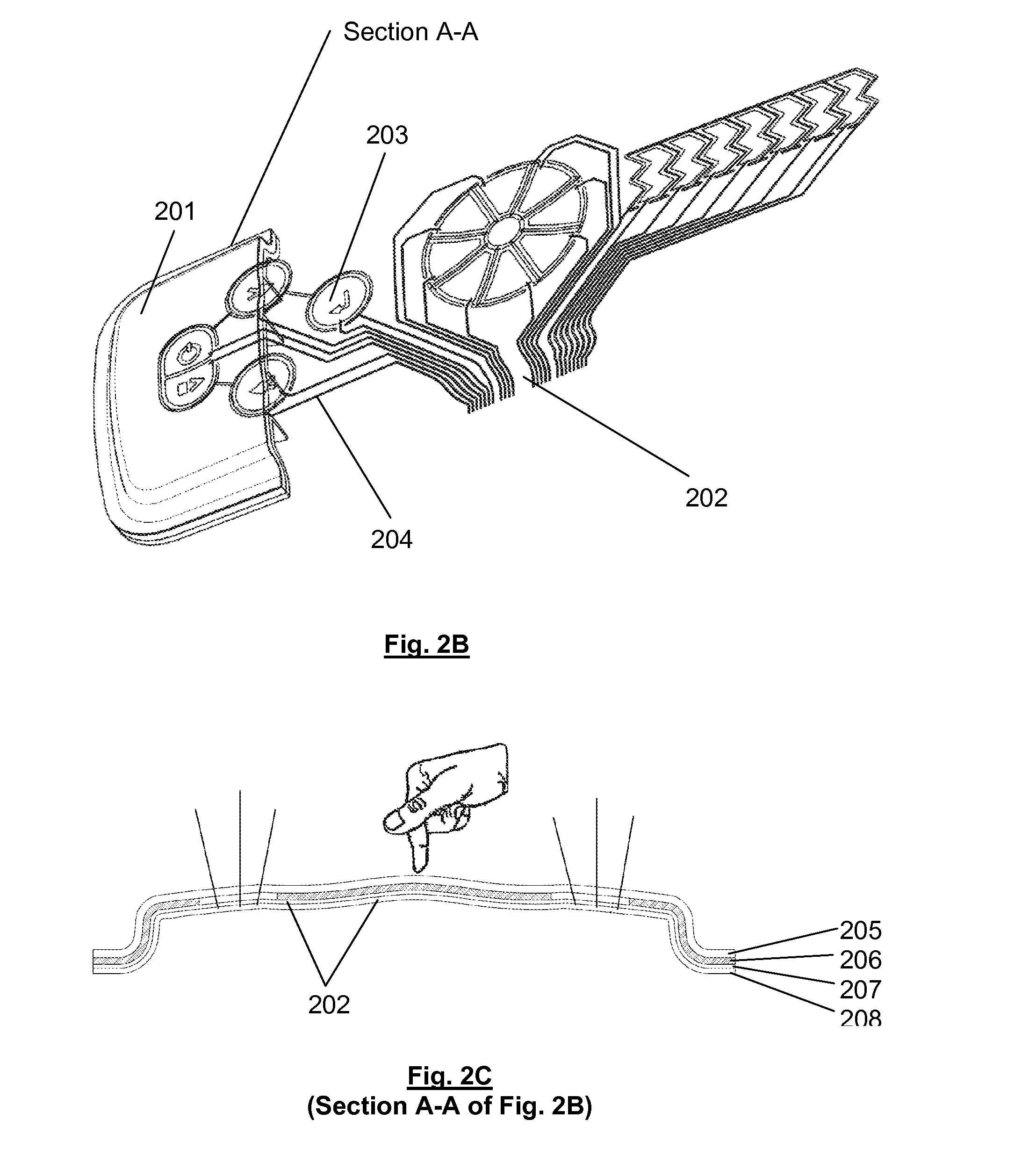
[0046]In an embodiment, a true 3-D moulded article including contours spanning sensing is shown in FIGS. 2A and 2B. A touch panel assembly 200 includes a moulded panel 201 having a functional layer 202, such as an electrical layer made from conductive paste. The functional layer 202 can be a paste configured so as to allow additional flexibility and workability while maintaining characteristics such as conductivity. FIM processes are commonly used for printing decorative designs; the decorative printed surface can be used to apply the functional layer 202, such as by a silkscreen printing process or inkjet printing.

[0047]After the printing process for the functional layer 202 is completed, the functional layer 202 can be formed and worked, such as moulded into the moulded panel 201 to form the touch panel assembly 200. Initial forming or shaping can refer to processes that are used to shape the film permanently include processes such as high pressure forming, thermoforming and the l...


PUM

PropertyMeasurementUnit
Lengthaaaaaaaaaa
Lengthaaaaaaaaaa
Lengthaaaaaaaaaa

Abstract

A method comprising: patterning one or more electrical layers on a substrate; shaping the patterned substrate into a 3-dimensional contour, wherein the contour including a significant change in gradient in or adjacent to one or more sensing areas of the electrical layer, and over-moulding the shaped substrate, wherein degradation of a trace in the electrical layer at or adjacent to the one or more sensing areas during shaping and/or over-moulding is substantially minimised based on the width of the trace, the thickness or number of layers of the trace, the bending radius of the trace, the material of the trace, and/or a primer over layer on the trace.

Description

FIELD OF THE INVENTION[0001]The present invention relates generally to a method of moulding.BACKGROUND[0002]Electronic interfaces are commonly used in a wide range of applications from consumer products including computer systems, game consoles, electrical appliances, in-vehicle systems including automotive consoles or central stacks and wheel mounted controls, portable devices including audio devices, multimedia players, cellular phones or the like, to industrial control consoles, switches, or the like. While mechanical buttons, switches, contacts and the like have typically been used in connection with conventional electronic input devices, there has been a shift away from the use of mechanical buttons, switches and the like toward low activation pressure technologies such as touch sensitive switches. Integrating touch sensor technologies into input devices in connection with products such as touch panels, touch screens, and capacitive keypads and the like has increased due to the...

Claims


Application Information

Patent Timeline
IPC IPC(8): H05K3/10H05K7/02
CPCH05K7/02H05K3/10B29C45/14811B29C45/1671B29C53/04B29L2031/3437B32B2457/00H03K17/9622H03K2217/960755H03K2217/960785Y10T29/49117Y10T29/49155Y10T29/49156B29C45/14B32B37/18H03K17/96
Inventor LEONG, CHEE SENGCHUA, SZE LAM
Owner FISCHER TECH
Why Eureka
Try Eureka