Yaw-rate sensor

a sensor and yaw rate technology, applied in the field of yaw rate sensors, can solve the problems of reducing the space and power requirements of the electronic evaluation circuit, and achieve the effects of reducing the susceptibility of interference of the yaw-rate sensor, reducing the space and power requirements of the electronic evaluation circuit, and advantageously manufacturing cost-effectively

Active Publication Date: 2012-03-15
ROBERT BOSCH GMBH
View PDF1 Cites 77 Cited by
  • Summary
  • Abstract
  • Description
  • Claims
  • Application Information

AI Technical Summary

Benefits of technology

[0009]Because the substructures are mechanically coupled, the yaw-rate sensor advantageously has a defined, shared drive mode and, therefore, requires only one drive control circuit. This reduces the space and power requirements for the electronic evaluation circuit.
[0018]The biaxial and triaxial yaw-rate sensors provided by the present invention may be advantageously manufactured cost-effectively and by mass production using standard surface micromachining processes.

Problems solved by technology

This reduces the space and power requirements for the electronic evaluation circuit.

Method used


Image

  • Yaw-rate sensor
  • Yaw-rate sensor
  • Yaw-rate sensor

Examples


Embodiment Construction

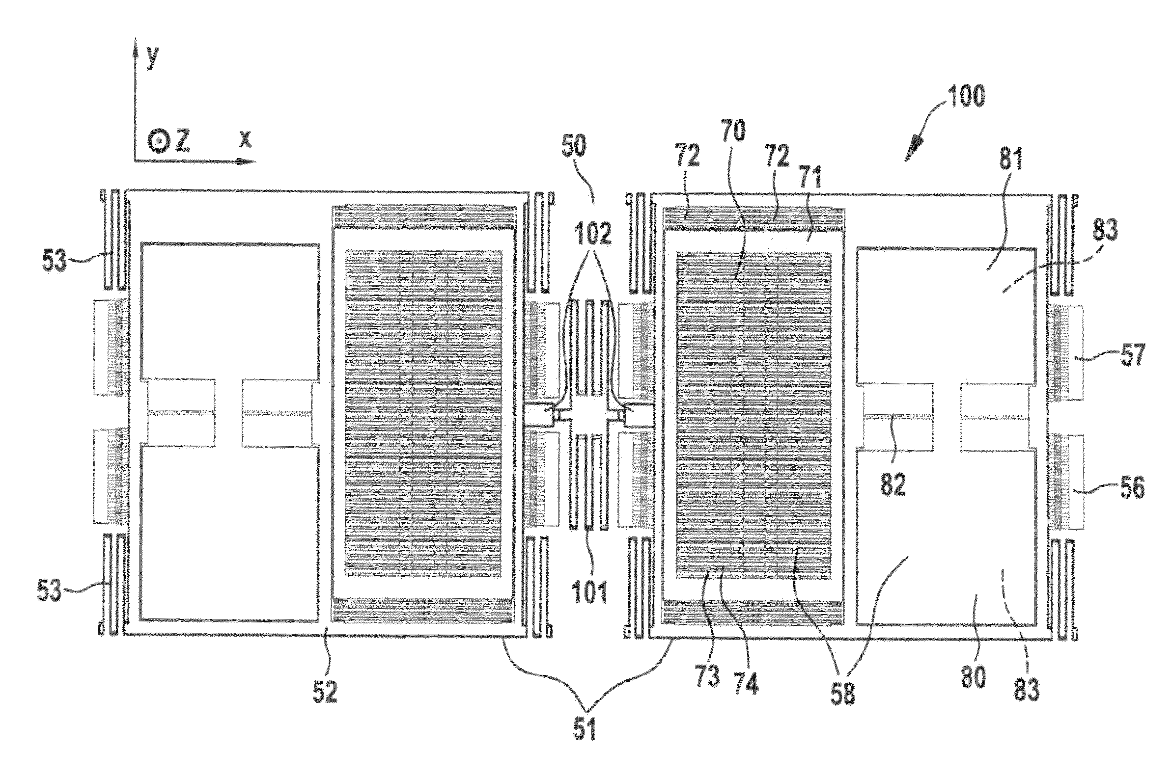
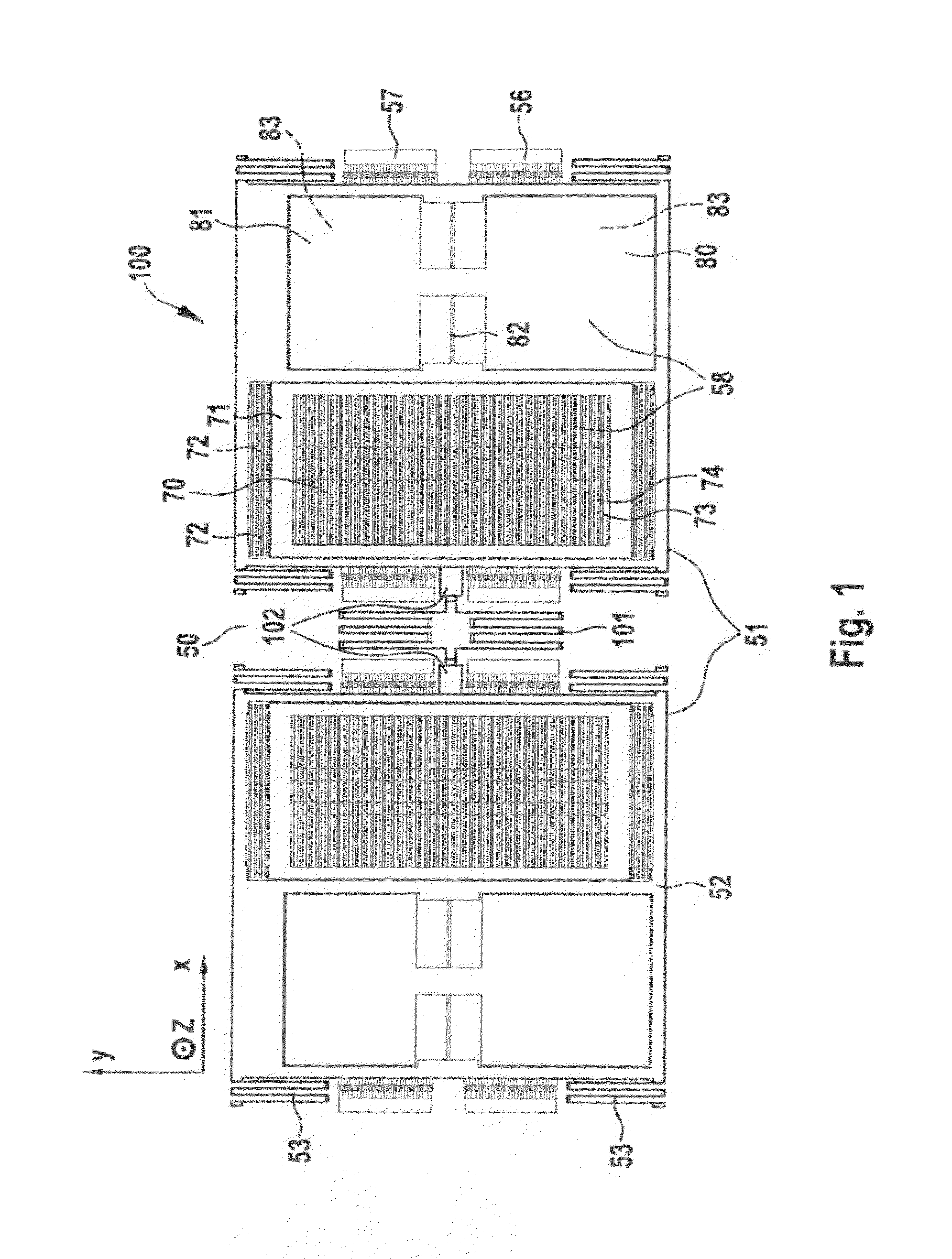
[0037]FIG. 1 shows a view of a biaxial yaw-rate sensor 100. Yaw-rate sensor 100 includes two movable substructures 51 which are mounted over a substrate 50 that extends in the plane of the paper. The edge length of yaw-rate sensor 100 is a few hundred micrometers.

[0038]Movable substructures 51 are manufactured out of a material that, at the very bottom, has a thick silicon substrate upon which there is an oxide layer. Above the oxide layer, there is a polysilicon layer VP that forms a circuit trace plane. This is followed by another oxide layer OX, upon which a silicon layer EP is deposited, out of which the movable components of the yaw-rate sensors are manufactured. Recesses are provided at special sites in oxide layer OX. Connections between silicon layer EP and circuit trace plane VP are formed in these recesses during deposition of silicon layer EP. The sensor elements are then defined, and oxide layer OX is removed in an etching process. Self-supporting structures are thereby ...


PUM


Abstract

A yaw-rate sensor having a substrate and a plurality of movable substructures that are mounted over a surface of the substrate, the movable substructures being coupled to a shared, in particular, central spring element, means being provided for exciting the movable substructures into a coupled oscillation in a plane that extends parallel to the surface of the substrate, the movable substructures having Coriolis elements, means being provided for detecting deflections of the Coriolis elements induced by a Coriolis force, a first Coriolis element being provided for detecting a yaw rate about a first axis, a second Coriolis element being provided for detecting a yaw rate about a second axis, the second axis being oriented perpendicularly to the first axis.

Description

BACKGROUND OF THE INVENTION[0001]1. Field of the Invention[0002]The present invention relates to a yaw-rate sensor.[0003]2. Description of Related Art[0004]Linearly oscillating yaw-rate sensors are generally known. In these yaw-rate sensors, parts of the sensor structure are actively set into oscillation (primary oscillation) in one direction, i.e., along a first axis (x-axis) that is oriented parallel to a substrate surface. In response to an external yaw rate about one particular sensitive axis, Coriolis forces act on the oscillating parts of the sensor structure. These Coriolis forces, which vary periodically with the frequency of the primary oscillation, induce oscillations in parts of the sensor structure (secondary oscillation) in the direction of a second axis that is oriented perpendicularly to the x-axis. The second axis can be oriented parallel to the substrate surface or perpendicularly to the substrate surface. Detection means, which capacitively sense the secondary osci...

Claims


Application Information

Patent Timeline
Patent Type & Authority Applications(United States)
IPC IPC(8): G01P3/44F16F3/00G01C19/56
CPCG01C19/574G01P3/44F16F1/025G01C19/5747
Inventor NEUL, REINHARDCLASSEN, JOHANNESOHMS, TORSTENKUHLMANN, BURKHARDFRANKE, AXELKOHN, OLIVERMEISEL, DANIEL CHRISTOPHHAUER, JOERGGOMEZ, UDO-MARTINKEHR, KERSTEN
Owner ROBERT BOSCH GMBH
Why Eureka
Try Eureka