Planetary gear mechanism for a wind power plant

a technology of wind power plants and gear mechanisms, applied in the direction of bearings, shafts, engine fuctions, etc., to achieve the effect of effective lubrication

Active Publication Date: 2012-05-03
FLENDER GMBH
View PDF6 Cites 76 Cited by
  • Summary
  • Abstract
  • Description
  • Claims
  • Application Information

AI Technical Summary

Benefits of technology

[0009]According to one preferred embodiment of the present invention, in each case two bores, which start from the oil reservoir, extend radially and end at the sleeve, are provided in the planetary gear shafts. Furthermore, the sleeves have, in regions in which the bores starting from the oil reservoir end,...

Problems solved by technology

The reasons for this are frequently occurring transient operating conditions and tempor...

Method used


Image

  • Planetary gear mechanism for a wind power plant
  • Planetary gear mechanism for a wind power plant
  • Planetary gear mechanism for a wind power plant

Examples


first embodiment

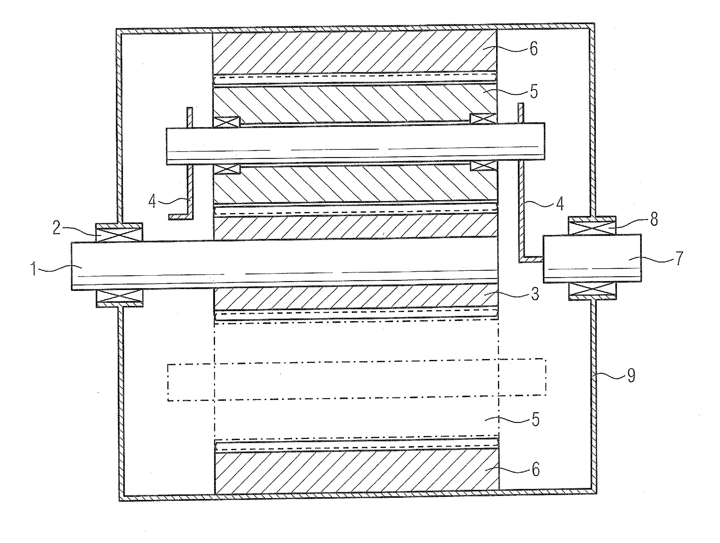
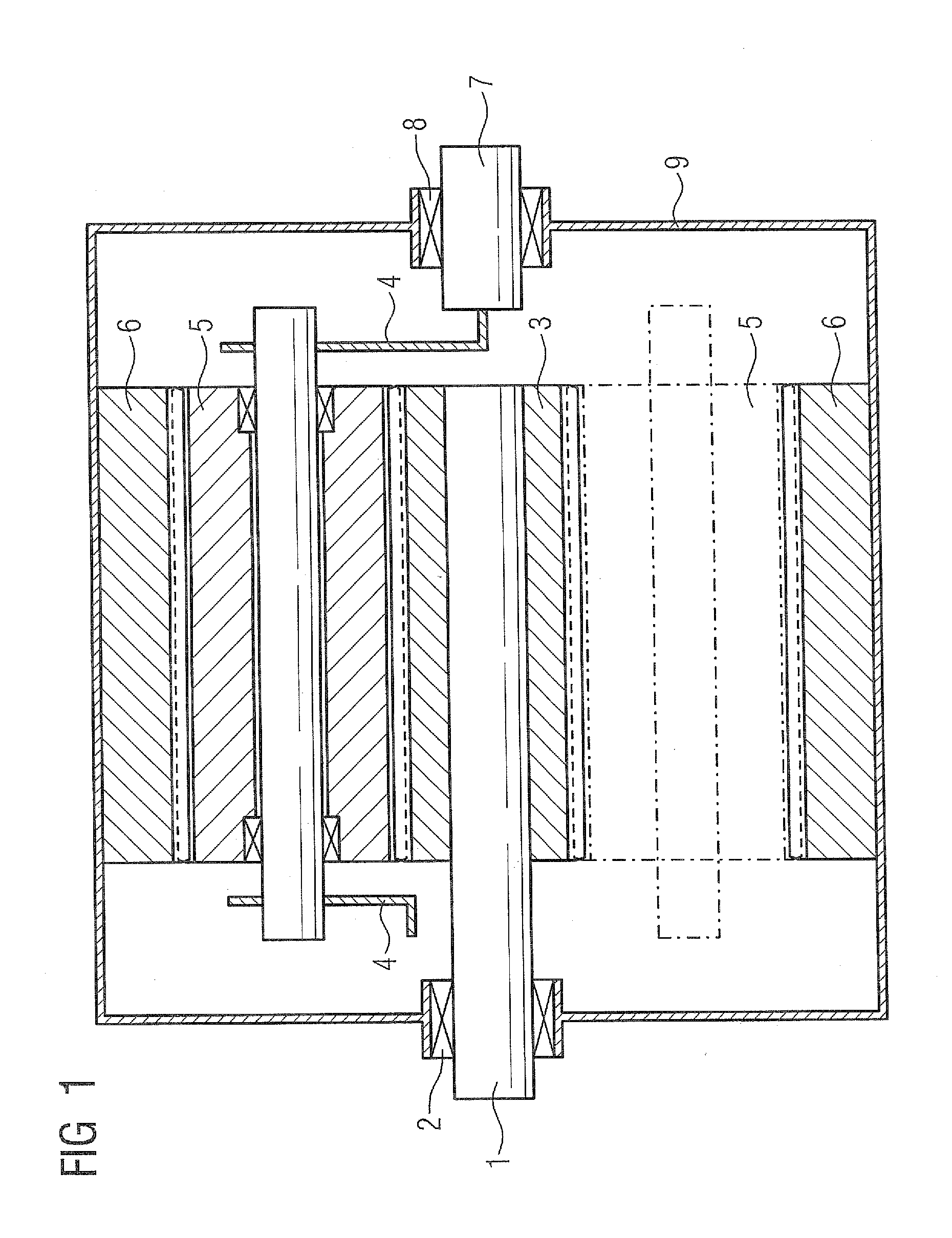
[0022]FIG. 2 illustrates a planetary carrier 4 with a planetary gear 5 for a planetary gear mechanism according to FIG. 1 in longitudinal section. A plurality of radial slide bearings, which each include a sleeve 108 made of a slide bearing material, are provided for supporting the planetary gears 5. variant, the sleeve 108 is attached as an inner ring to a planetary gear shaft 104. An associated outer bearing ring is formed by a bore in the planetary gear 5 made from a material suitable for teeth.

[0023]The sleeve 108 can be connected in a frictionally locking, positively locking or materially joined fashion to the planetary gear shaft 104. If the sleeve 108 is connected in a materially joined fashion to the planetary gear shaft 104, it is preferably formed by coating the planetary gear shaft 104 with a slide bearing material. In the case of a frictionally locking connection, the sleeve 108 can be additionally secured by means of one or more securing pins 115.

[0024]The planetary ge...

second embodiment

[0033] variant illustrated in FIG. 9, the sleeve 208 and / or a bushing is mounted as an outer ring of a radial slide bearing in a bore in a planetary gear 5. Accordingly, an associated inner bearing ring is formed by the planetary gear shaft 204. The sleeve 208 can be connected in a frictionally locking, positively locking or materially joined fashion to the planetary gear 5. If the sleeve 208 is connected in a materially joined fashion to the planetary gear 5, it is preferably formed by coating the planetary gear 5 with a slide bearing material. Furthermore, the sleeve 208 can be embodied as a single component or as multiple components.

[0034]The sleeve 208 has end faces which are oriented with respect to the planetary carrier cheeks 206 and which serve as first bearing elements of an axial slide bearing. The two end faces each run against guide disks 205, which are connected as second bearing elements to the planetary carrier cheeks 206 in a frictionally locking or positively lockin...


PUM


Abstract

A planetary gear mechanism for a wind power plant includes a sun gear, an internal gear and a planetary carrier with planetary gears supported by radial and axial slide bearings. The radial slide bearings include a sleeve made of a slide bearing material and attached as an inner ring to a planetary gear shaft or mounted as an outer ring in a bore in a planetary gear. An outer bearing ring cooperating with the inner ring is formed by the bore in the planetary gear, or an inner bearing ring cooperating with the outer ring is formed by the planetary gear shaft. A slide bearing material of a first bearing element of the axial slide bearings is applied between a planetary carrier cheek and an end side of a planetary gear. The end side of the planetary gear or the planetary carrier cheek forms a corresponding cooperating second bearing element.

Description

CROSS-REFERENCES TO RELATED APPLICATIONS[0001]This application claims the priority of European Patent Application, EP10004567, filed Apr. 30, 2010, pursuant to 35 U.S.C. 119(a)-(d), the content of which is incorporated herein by reference in its entirety as if fully set forth herein.BACKGROUND OF THE INVENTION[0002]The present invention relates to a planetary gear mechanism for a wind power plant.[0003]The following discussion of related art is provided to assist the reader in understanding the advantages of the invention, and is not to be construed as an admission that this related art is prior art to this invention.[0004]Gear mechanisms for wind power plants were until now predominantly constructed with roller bearings. Slide bearings have previously been used only very rarely. The reasons for this are frequently occurring transient operating conditions and temporarily extremely low sliding speeds with simultaneous extreme stressing of the slide bearings. Conventional slide bearin...

Claims


Application Information

Patent Timeline
IPC IPC(8): F16H57/04F16H57/08
CPCF05B2260/40311F03D80/70F16H57/0479F16H57/0486F16H57/082F16C32/0659F16C32/0685F16C33/1055F16H2057/085Y02E10/722F16C2361/61F03D15/00F16C17/02F16C17/04F16C2360/31F03D15/10F16C17/26Y02E10/72
Inventor DINTER, RALF MARTINKLEIN-HITPASS, ARNOMEYER, THOMAS
Owner FLENDER GMBH
Why Eureka
Try Eureka