Radially pressure balanced floating seal system

a floating seal and pressure-balanced technology, applied in the direction of engine seals, leakage prevention, machines/engines, etc., can solve the problems of unbalanced radial or side force on the seal housing, and the pressure environment may not permit the floating seal to float freely, so as to minimize the potential of rubbing and failure

Inactive Publication Date: 2002-08-13
THE UNITED STATES OF AMERICA AS REPRESENTED BY THE SECRETARY OF THE NAVY
View PDF9 Cites 18 Cited by
  • Summary
  • Abstract
  • Description
  • Claims
  • Application Information

AI Technical Summary

Benefits of technology

One object of the present invention is a radially pressure balan

Problems solved by technology

In floating seal housings, however, standard canted O-ring seals have resulted in an unbalanced radial or side force on the seal housings.
If the system is not axially pressure balanced, the net axial force in a pressurized environment may not permit the. floating seal housing to flo

Method used


Image

  • Radially pressure balanced floating seal system
  • Radially pressure balanced floating seal system
  • Radially pressure balanced floating seal system

Examples


Embodiment Construction

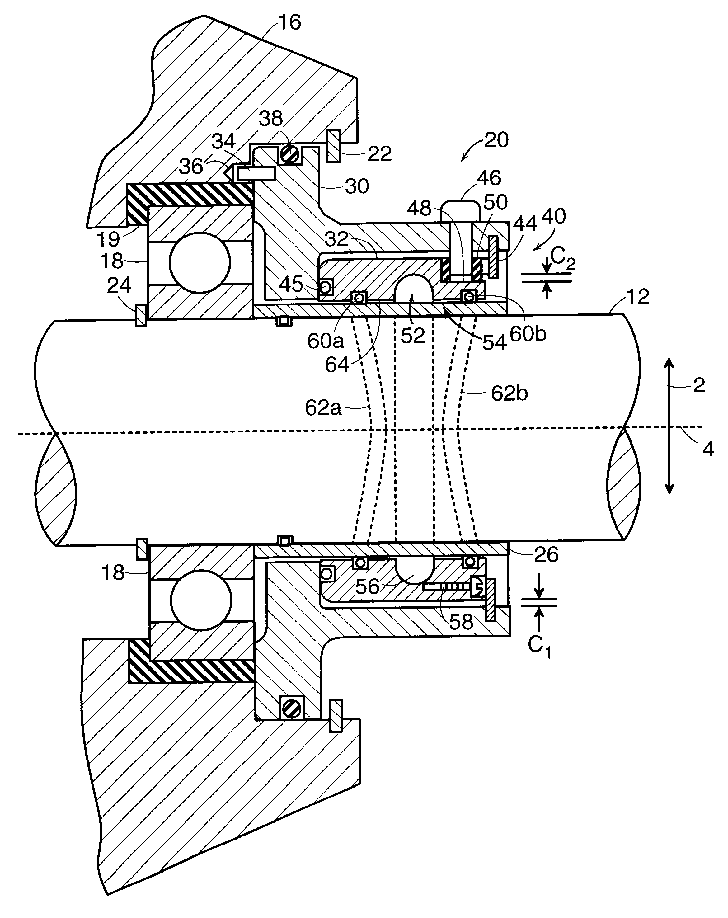
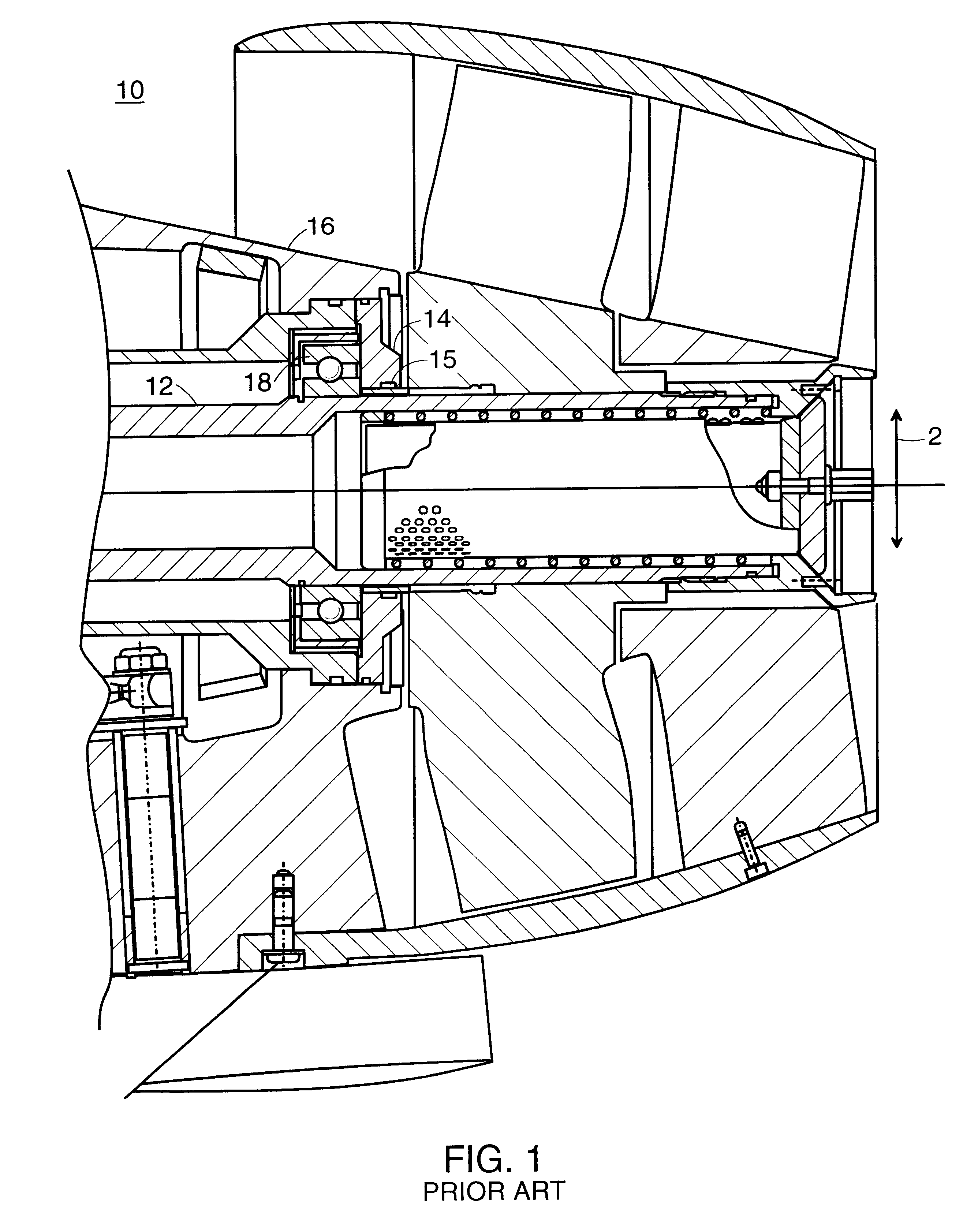
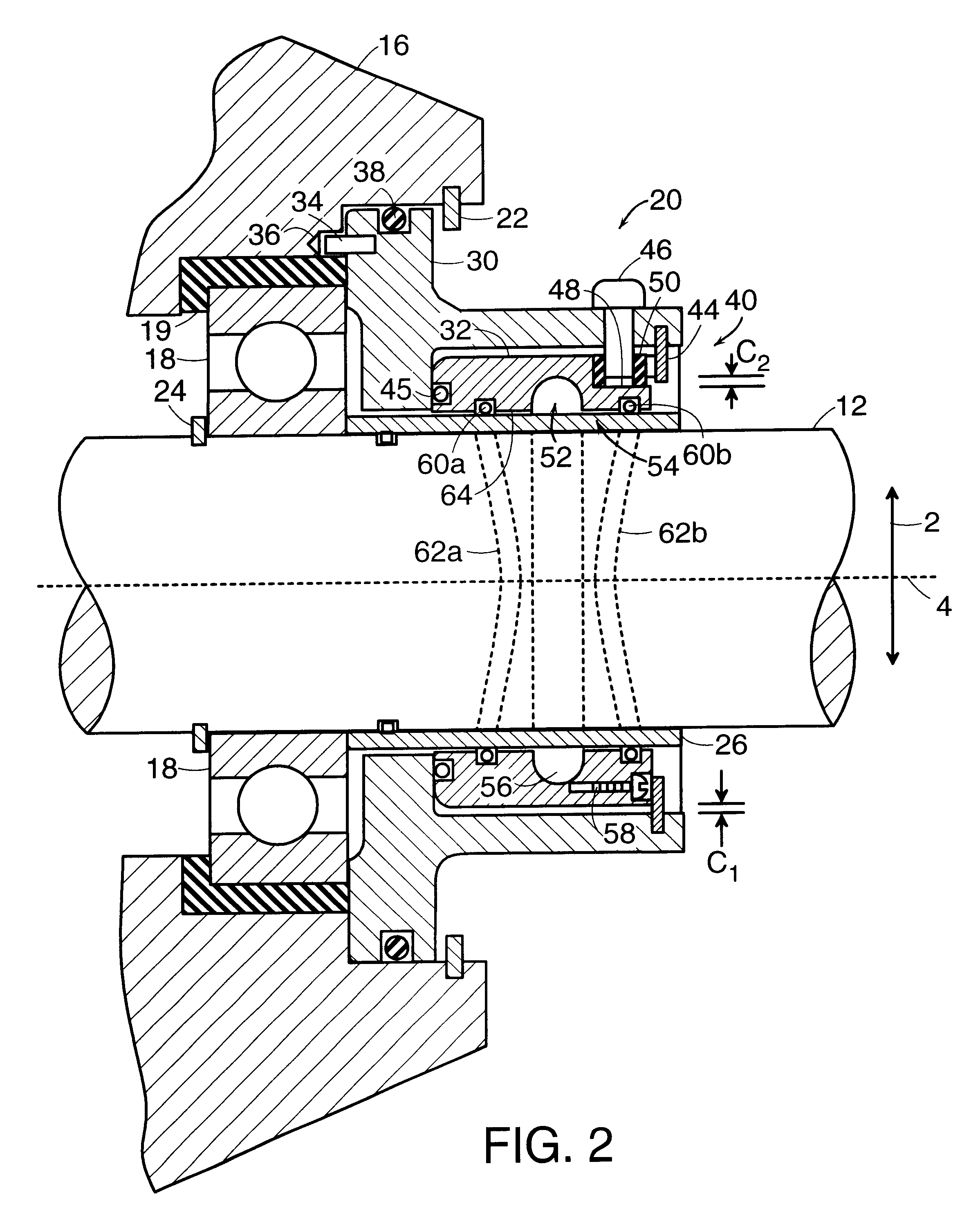
A radially pressure balanced floating seal system 20, FIG. 2, according to the present invention, is used to seal a rotating shaft 12 while allowing movement of the shaft in a radial direction 2. In one example, the floating seal system 20 is assembled in a tail cone housing 16 of a torpedo proximate the shaft bearings 18, which are preferably mounted in a resilient elastomer 19. The floating seal system 20 is held in place by a spiral ring 22 or other similar retaining member or mechanism, and the bearings 18 are held in place by a retaining ring 24 or other similar retaining member or mechanism. A seal ring 26 made of ground and polished, hard, chrome-plated, stainless steel or alternative compatible material is preferably disposed around the shaft 12 and between the shaft 12 and the floating seal system 20. The present invention contemplates other uses for the floating seal system 20 in other types of vehicles or with rotating shafts in other types of machines.

The floating seal s...


PUM


Abstract

A radially pressure balanced floating seal system is used to seal a rotating shaft, such as a drive shaft in a torpedo, or other type of vehicle or machinery. The radially pressure balanced floating seal includes an outer seal housing and an inner seal housing that floats with respect to the outer seal housing. The outer seal housing is secured proximate the shaft bearings, for example, in the tail cone of a torpedo. The inner seal housing is secured within an internal recessed region in the outer seal housing, and two or more discrete torque members or one distributed torque member extend from the outer seal housing to the inner seal housing to prevent rotation of the inner seal housing while allowing movement generally in a radial direction. The inner seal housing includes a lubricant recess formed within an internal annular aperture of the inner seal housing for containing lubricant. Double canted O-rings are disposed on each side of the lubricant recess in double canted O-ring grooves. The double canted grooves and O-rings prevent unbalanced radial forces that might cause rubbing of the shaft against the seal housing. In one embodiment, the lubricant recess is double canted to also minimize the sealing length.

Description

STATEMENT OF GOVERNMENT INTERESTThe invention described herein may be manufactured and used by or for the Government of the United States of America for governmental purposes without the payment of any royalties thereon or therefore.CROSS-REFERENCE TO RELATED PATENT APPLICATIONThis patent application is co-pending with two related patent applications filed on the same date, entitled: COMPACT DRIVE SHAFT FLOATING SEAL SYSTEM, and AXIALLY PRESSURE BALANCED FLOATING SEAL SYSTEM, both having the same inventors as this patent application.BACKGROUND OF THE INVENTION(1) Field of the InventionThe present invention relates to sealing assemblies used on rotating shafts and more particularly, relates to a radially pressure balanced floating seal system used on a drive shaft.(2) Description of the Prior ArtO-ring seals are commonly used to seal rotating shafts used in vehicles or machinery. For example, in an existing torpedo tail cone assembly 10, FIG. 1, the drive shaft 12 of the torpedo is t...

Claims


Application Information

Patent Timeline
IPC IPC(8): F16J15/44F16J15/16
CPCF16J15/162F16J15/441
Inventor AMARAL, ANTONIO M.OLSON, STANLEY J.
Owner THE UNITED STATES OF AMERICA AS REPRESENTED BY THE SECRETARY OF THE NAVY
Why Eureka
Try Eureka