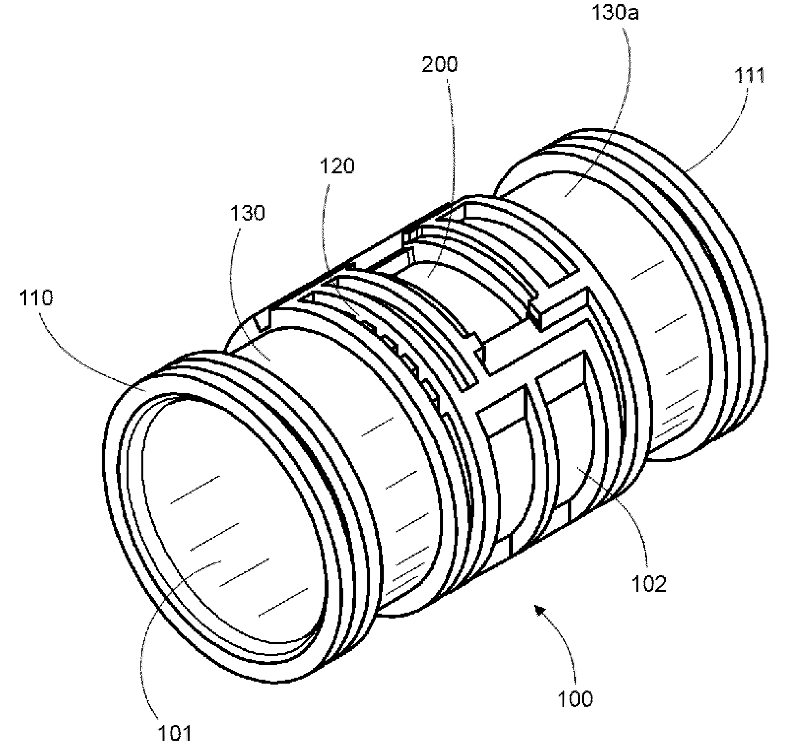
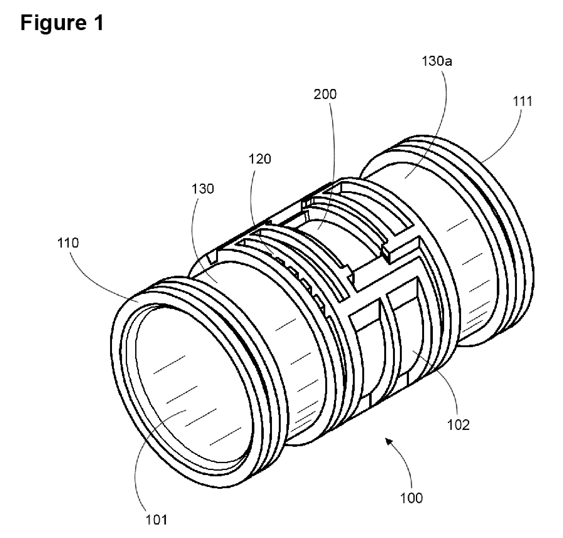
[0013]One or more embodiments of the invention enable an internally pressure compensated non-clogging drip emitter. Embodiments include an emitter body having an inner portion that includes an inner surface, an outer portion that contacts an enclosing pipe and that includes an outer surface, a first end and a second end, an inlet that comprises a filter or a place holder for a fluid retainment valve, a labyrinth coupled with the outer surface, a compensating chamber formed within an inner portion of the drip emitter, a compensating surface formed inside the compensating chamber, a
pool coupled with the outer surface wherein the
pool is configured to hold fluid when the emitter body is enclosed in the enclosing pipe, a fluid flow path leading from the inner portion to the outer portion of the drip emitter wherein the drip emitter is configured to allow the fluid to flow from the inlet, through the labyrinth, through the compensating chamber and to the
pool through the fluid flow path. The more of the labyrinth that is sealed to air by the water retainment valve, the more resistant to clogging the drip emitter embodiment is. For example, mud cannot flow back into the drip emitter, and air cannot
creep into the labyrinth, and hence water that contains suspended iron does not form
rust. Hence, the protected internal components of the drip emitter are protected from the elements, which thus prevents clogging.
[0016]Embodiments of the invention may be configured with a pressure compensating chamber (otherwise known as a compensating chamber herein) that is configured to allow pressure from the water in the emitter to limit a compressible element or deformable element that in effect controls the output pressure and / or flow of water from the emitter. In one or more embodiments of the invention, the compensating chamber is formed together with the water retainment valve in an integrated unit although this is not required. In one or more embodiments of the invention, the compensating chamber may be configured in such a way that there is minimal or no contact of the deformable element against the inside of the enclosing pipe. In this embodiment, the pressure compensating chamber is formed within the drip emitter, for example as part of a two-shot injection mold manufacturing process. This embodiment provides advantages of consistency since the enclosing pipe forms no direct portion of the pressure compensating chamber. In addition, this embodiment requires no manual labor or
machine assembly to assemble and bypasses the need for ISO conditioning to properly seat the pressure compensating membrane as is required with known devices.
[0017]An embodiment of the method of producing the drip emitter includes selecting a first material for injection molding for an emitter body, selecting a second material for injection molding wherein the second material comprises an elastomeric material to effect regulation of the drip emitter, injecting an injection mold with a the first material and the second material in separate shots in a single mold to form the drip emitter, and, cross-linking the second material to increase elasticity of the second material after injection but before inserting the drip emitter into a pipe. The method may also include forming a water retainment valve with the second material in the single mold, forming a ventable / anti-
siphon / anti-drain water retainment valve with the second material in the single mold, optionally forming a mechanical engagement between the first material and the second material wherein the mechanical engagement comprises at least one
interlocking element formed into the first material and corresponding at least one
interlocking element formed into the second material. In addition, the method for producing the drip emitter may include forming a water retainment valve that is configured to hinder or allow no
backflow of air or water into the drip emitter when a pressure internal to the drip emitter is below the pressure external to the pipe. In one or more embodiments, the compensating element is injection molded into a portion of the drip emitter and does not operate against or require the support of the enclosing pipe or wherein the compensating surface does not depend on or require the pipe when the compensating membrane is deformed in operation against the compensating surface.
[0023]Embodiments of the invention or method of producing embodiments of the invention may optionally utilize an inwardly projecting filter prevent clogging when the emitter oriented rotationally downward in the field as the filter is not a
potential well and hence
sediment does not drop into it. In addition, inwardly projecting filter embodiments provide a snorkel effect that enables faster moving and cleaner water to enter the emitter via the filter, hence eliminating the potential to clog in a second manner. Thus inwardly projecting filter embodiments eliminate clogs in two ways, by avoiding
sediment with a height offset and avoiding
sediment by selecting faster moving water away from the pipe outer surface. An emitter may also utilize more than one filter in a redundant configuration to either supply both pools on each side of the emitter or alternatively to supply an associated pool in a one-to-one manner.
[0024]Embodiments of the invention may further include a pool coupled with the outer cylindrical surface wherein the pool is configured to hold water filtered by the filter or inwardly offset filter when the hollow cylindrical emitter body is enclosed in a pipe. Embodiments further include a labyrinth coupled with the outer cylindrical surface wherein the labyrinth may optionally maximize use of turbulent transfer zones, at least after water enters the labyrinth, and wherein the labyrinth allows the water to flow from the filter or filter to the pool. Through the use of turbulent transfer zones once the water enters the labyrinth, sediment is continuously forced through the labyrinth and has no location to settle and hence the labyrinth minimizes the potential to clog. In other words, laminar flow transfer zones are avoided as these type of “straight” paths tend to clog over time with sediments. By utilizing a filter or an inwardly offset filter and a labyrinth that avoids laminar flow zones, embodiments of the invention so configured minimize the potential to clog in multiple ways.
[0026]In one or more embodiment of the invention, a symmetrical embodiment may be utilized that provides two pools, two labyrinths and optionally two pressure compensation and / or two water retainment valves. This embodiment provides a robust redundant embodiment that continues to work even if one labyrinth were to clog, or if one hole into the pipe associated with a particular emitter were to be externally plugged, buried or blocked. Several embodiments of redundant configurations may be formed that include a two pool embodiment with one or more labyrinths, i.e., one labyrinth with a “T” or fork section, or two labyrinths, each flowing to a separate pool. Alternatively, the embodiment can be doubled to form more than one filter or inwardly offset filter, for example offset rotationally by 180 degrees, with separate labyrinth(s) and pool(s) coupled therewith for even more redundancy.

