Pressure compensated non-clogging drip emitter

a drip emitter and non-clogging technology, applied in the field of irrigation equipment, can solve the problems of not being able to easily roll up the pipe, and achieve the effect of resisting clogging and preventing clogging

Inactive Publication Date: 2013-02-12
MAMO SHAY
View PDF31 Cites 15 Cited by
  • Summary
  • Abstract
  • Description
  • Claims
  • Application Information

AI Technical Summary

Benefits of technology

[0013]One or more embodiments of the invention enable a pressure compensated non-clogging drip emitter. Embodiments include an emitter body having an inner surface, an outer surface, a first end and a second end, a filter, a pool coupled with the outer surface wherein the pool is configured to hold water filtered by the filter when the emitter body is enclosed in a pipe, a labyrinth coupled with the outer surface wherein the labyrinth allows the water to flow from the filter to the pool through a water flow path and, a water retainment valve situated after an initial portion of the labyrinth and in the water flow path. The more of the labyrinth that is sealed to air by the water retainment valve, the more resistant to clogging the drip emitter embodiment is. For example, mud cannot flow back into the drip emitter, and air cannot creep into the labyrinth, and hence water that contains suspended iron does not form rust. Hence, the protected internal components of the drip emitter are protected from the elements, which thus prevents clogging.
[0017]An embodiment of the method of producing the drip emitter includes selecting a first material for injection molding for an emitter body, selecting a second material for injection molding wherein said second material comprises an elastomeric material to effect regulation of the drip emitter, injecting an injection mold with a said first material and said second material in separate shots in a single mold to form the drip emitter, and, cross-linking said second material to increase elasticity of said second material after injection but before inserting said drip emitter into a pipe. The method may also include forming a water retainment valve with said second material in the single mold, forming a ventable water retainment valve with said second material in the single mold, forming a mechanical engagement between said first material and said second material, forming a mechanical engagement between said first material and said second material wherein said mechanical engagement comprises at least one interlocking element formed into said first material and corresponding at least one interlocking element formed into said second material. In addition, the method for producing the drip emitter may include forming a water retainment valve that is configured to hinder or allow no backflow of air or water into the drip emitter when a pressure internal to the drip emitter is below the pressure external to the pipe.
[0022]Embodiments of the invention or method of producing embodiments of the invention may optionally utilize an inwardly projecting filter prevent clogging when the emitter oriented rotationally downward in the field as the filter is not a potential well and hence sediment does not drop into it. In addition, inwardly projecting filter embodiments provide a snorkel effect that enables faster moving and cleaner water to enter the emitter via the filter, hence eliminating the potential to clog in a second manner. Thus inwardly projecting filter embodiments eliminate clogs in two ways, by avoiding sediment with a height offset and avoiding sediment by selecting faster moving water away from the pipe outer surface. An emitter may also utilize more than one filter in a redundant configuration to either supply both pools on each side of the emitter or alternatively to supply an associated pool in a one-to-one manner.
[0023]Embodiments of the invention may further include a pool coupled with the outer cylindrical surface wherein the pool is configured to hold water filtered by the filter or inwardly offset filter when the hollow cylindrical emitter body is enclosed in a pipe. Embodiments further include a labyrinth coupled with the outer cylindrical surface wherein the labyrinth may optionally maximize use of turbulent transfer zones, at least after water enters the labyrinth, and wherein the labyrinth allows the water to flow from the filter or filter to the pool. Through the use of turbulent transfer zones once the water enters the labyrinth, sediment is continuously forced through the labyrinth and has no location to settle and hence the labyrinth minimizes the potential to clog. In other words, laminar flow transfer zones are avoided as these type of “straight” paths tend to clog over time with sediments. By utilizing a filter or an inwardly offset filter and a labyrinth that avoids laminar flow zones, embodiments of the invention so configured minimize the potential to clog in multiple ways.
[0025]In one or more embodiment of the invention, a symmetrical embodiment may be utilized that provides two pools, two labyrinths and optionally two pressure compensation and / or two water retainment valves. This embodiment provides a robust redundant embodiment that continues to work even if one labyrinth were to clog, or if one hole into the pipe associated with a particular emitter were to be externally plugged, buried or blocked. Several embodiments of redundant configurations may be formed that include a two pool embodiment with one or more labyrinths, i.e., one labyrinth with a “T” or fork section, or two labyrinths, each flowing to a separate pool. Alternatively, the embodiment can be doubled to form more than one filter or inwardly offset filter, for example offset rotationally by 180 degrees, with separate labyrinth(s) and pool(s) coupled therewith for even more redundancy.

Problems solved by technology

Ventable embodiments allow for the enclosing pipe to be rolled up for example while non-drain embodiments do not allow air into the pipe and hence do not allow for easily rolling up the pipe.

Method used


Image

  • Pressure compensated non-clogging drip emitter
  • Pressure compensated non-clogging drip emitter
  • Pressure compensated non-clogging drip emitter

Examples


Embodiment Construction

[0091]A pressure compensated non-clogging drip emitter will now be described. In the following exemplary description numerous specific details are set forth in order to provide a more thorough understanding of embodiments of the invention. It will be apparent, however, to an artisan of ordinary skill that the present invention may be practiced without incorporating all aspects of the specific details described herein. In other instances, specific features, quantities, or measurements well known to those of ordinary skill in the art have not been described in detail so as not to obscure the invention. Readers should note that although examples of the invention are set forth herein, the claims, and the full scope of any equivalents, are what define the metes and bounds of the invention.

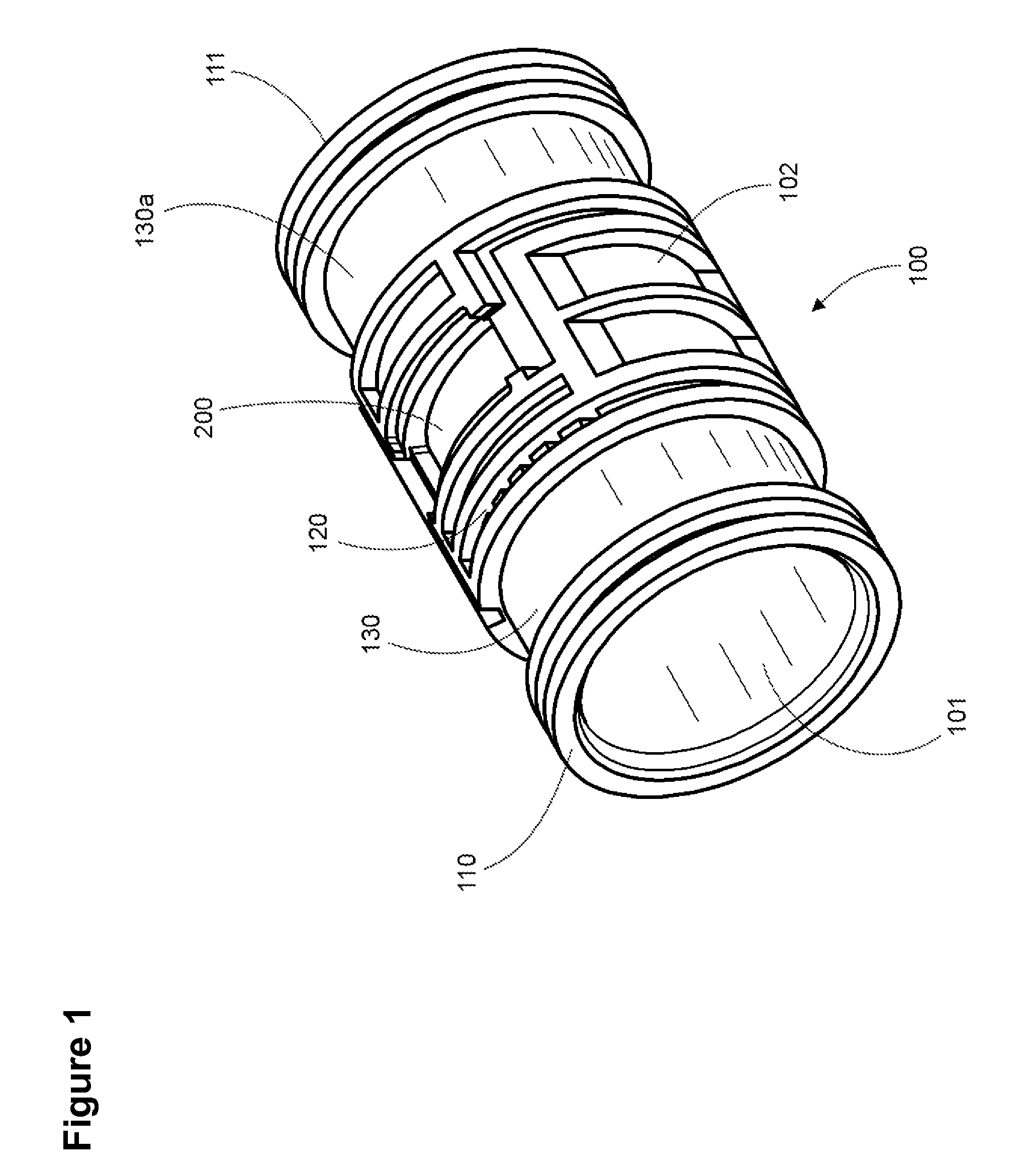
[0092]FIG. 1 is a perspective view of an embodiment of drip emitter 100. Embodiments include an emitter body having inner surface 101, outer surface 102 that forms the floor of the emitter working eleme...


PUM

PropertyMeasurementUnit
pressureaaaaaaaaaa
inner diameteraaaaaaaaaa
heightaaaaaaaaaa

Abstract

A drip emitter that utilizes one or more filters and one or more labyrinths wherein the labyrinth couples the filter(s) to one or more water retainment valves that leads to at least one pool. Prevents clogging by eliminating air into the labyrinth via a water retainment valve that is situated after at least an initial portion of a labyrinth within the drip emitter. Includes non-drain, anti-siphon and ventable versions. Includes a method of two shot injection molding for embodiments of the drip emitter that include non-drain, anti-siphon and ventable variants.

Description

[0001]This application is a continuation in part of U.S. patent application Ser. No. 12 / 254,761 filed Oct. 20, 2008, now U.S. Pat. No. 7,988,076 the specification of which is hereby incorporated herein by reference.BACKGROUND OF THE INVENTION[0002]1. Field of the Invention[0003]Embodiments of the invention described herein pertain to the field of irrigation apparatus. More particularly, but not by way of limitation, one or more embodiments of the invention enable a pressure compensated non-clogging drip emitter.[0004]2. Description of the Related Art[0005]There are multiple types of irrigation drippers. Simple drippers exist that are inserted serially along pipe, either by forcing a hole into the pipe and placing the dripper on the outside of the pipe, or by cutting the pipe and inserting the dripper in line with the pipe. These systems require great amounts of labor when providing a watering system for a large agricultural area for example.[0006]Other types of drippers include drip...

Claims


Application Information

Patent Timeline
Patent Type & Authority Patents(United States)
IPC IPC(8): B29C45/16
CPCA01G25/023B29C45/1635B29C45/1676
Inventor MAMO, SHAY
Owner MAMO SHAY
Why Eureka
Try Eureka