Internally pressure compensated non-clogging drip emitter

a drip emitter and pressure compensation technology, applied in the field of irrigation equipment, can solve the problems of not being able to easily roll up the pipe, and achieve the effect of resisting clogging and preventing clogging

Inactive Publication Date: 2014-03-04
MAMO SHAY
View PDF26 Cites 21 Cited by
  • Summary
  • Abstract
  • Description
  • Claims
  • Application Information

AI Technical Summary

Benefits of technology

[0013]One or more embodiments of the invention enable an internally pressure compensated non-clogging drip emitter. Embodiments include an emitter body having an inner portion that includes an inner surface, an outer portion that contacts an enclosing pipe and that includes an outer surface, a first end and a second end, an inlet that comprises a filter or a place holder for a fluid retainment valve, a labyrinth coupled with the outer surface, a compensating chamber formed within an inner portion of the drip emitter, a compensating surface formed inside the compensating chamber, a pool coupled with the outer surface wherein the pool is configured to hold fluid when the emitter body is enclosed in the enclosing pipe, a fluid flow path leading from the inner portion to the outer portion of the drip emitter wherein the drip emitter is configured to allow the fluid to flow from the inlet, through the labyrinth, through the compensating chamber and to the pool through the fluid flow path. The more of the labyrinth that is sealed to air by the water retainment valve, the more resistant to clogging the drip emitter embodiment is. For example, mud cannot flow back into the drip emitter, and air cannot creep into the labyrinth, and hence water that contains suspended iron does not form rust. Hence, the protected internal components of the drip emitter are protected from the elements, which thus prevents clogging.
[0016]Embodiments of the invention may be configured with a pressure compensating chamber (otherwise known as a compensating chamber herein) that is configured to allow pressure from the water in the emitter to limit a compressible element or deformable element that in effect controls the output pressure and / or flow of water from the emitter. In one or more embodiments of the invention, the compensating chamber is formed together with the water retainment valve in an integrated unit although this is not required. In one or more embodiments of the invention, the compensating chamber may be configured in such a way that there is minimal or no contact of the deformable element against the inside of the enclosing pipe. In this embodiment, the pressure compensating chamber is formed within the drip emitter, for example as part of a two-shot injection mold manufacturing process. This embodiment provides advantages of consistency since the enclosing pipe forms no direct portion of the pressure compensating chamber. In addition, this embodiment requires no manual labor or machine assembly to assemble and bypasses the need for ISO conditioning to properly seat the pressure compensating membrane as is required with known devices.
[0017]An embodiment of the method of producing the drip emitter includes selecting a first material for injection molding for an emitter body, selecting a second material for injection molding wherein the second material comprises an elastomeric material to effect regulation of the drip emitter, injecting an injection mold with a the first material and the second material in separate shots in a single mold to form the drip emitter, and, cross-linking the second material to increase elasticity of the second material after injection but before inserting the drip emitter into a pipe. The method may also include forming a water retainment valve with the second material in the single mold, forming a ventable / anti-siphon / anti-drain water retainment valve with the second material in the single mold, optionally forming a mechanical engagement between the first material and the second material wherein the mechanical engagement comprises at least one interlocking element formed into the first material and corresponding at least one interlocking element formed into the second material. In addition, the method for producing the drip emitter may include forming a water retainment valve that is configured to hinder or allow no backflow of air or water into the drip emitter when a pressure internal to the drip emitter is below the pressure external to the pipe. In one or more embodiments, the compensating element is injection molded into a portion of the drip emitter and does not operate against or require the support of the enclosing pipe or wherein the compensating surface does not depend on or require the pipe when the compensating membrane is deformed in operation against the compensating surface.
[0023]Embodiments of the invention or method of producing embodiments of the invention may optionally utilize an inwardly projecting filter prevent clogging when the emitter oriented rotationally downward in the field as the filter is not a potential well and hence sediment does not drop into it. In addition, inwardly projecting filter embodiments provide a snorkel effect that enables faster moving and cleaner water to enter the emitter via the filter, hence eliminating the potential to clog in a second manner. Thus inwardly projecting filter embodiments eliminate clogs in two ways, by avoiding sediment with a height offset and avoiding sediment by selecting faster moving water away from the pipe outer surface. An emitter may also utilize more than one filter in a redundant configuration to either supply both pools on each side of the emitter or alternatively to supply an associated pool in a one-to-one manner.
[0024]Embodiments of the invention may further include a pool coupled with the outer cylindrical surface wherein the pool is configured to hold water filtered by the filter or inwardly offset filter when the hollow cylindrical emitter body is enclosed in a pipe. Embodiments further include a labyrinth coupled with the outer cylindrical surface wherein the labyrinth may optionally maximize use of turbulent transfer zones, at least after water enters the labyrinth, and wherein the labyrinth allows the water to flow from the filter or filter to the pool. Through the use of turbulent transfer zones once the water enters the labyrinth, sediment is continuously forced through the labyrinth and has no location to settle and hence the labyrinth minimizes the potential to clog. In other words, laminar flow transfer zones are avoided as these type of “straight” paths tend to clog over time with sediments. By utilizing a filter or an inwardly offset filter and a labyrinth that avoids laminar flow zones, embodiments of the invention so configured minimize the potential to clog in multiple ways.
[0026]In one or more embodiment of the invention, a symmetrical embodiment may be utilized that provides two pools, two labyrinths and optionally two pressure compensation and / or two water retainment valves. This embodiment provides a robust redundant embodiment that continues to work even if one labyrinth were to clog, or if one hole into the pipe associated with a particular emitter were to be externally plugged, buried or blocked. Several embodiments of redundant configurations may be formed that include a two pool embodiment with one or more labyrinths, i.e., one labyrinth with a “T” or fork section, or two labyrinths, each flowing to a separate pool. Alternatively, the embodiment can be doubled to form more than one filter or inwardly offset filter, for example offset rotationally by 180 degrees, with separate labyrinth(s) and pool(s) coupled therewith for even more redundancy.

Problems solved by technology

Ventable embodiments allow for the enclosing pipe to be rolled up for example while non-drain embodiments do not allow air into the pipe and hence do not allow for easily rolling up the pipe.

Method used


Image

  • Internally pressure compensated non-clogging drip emitter
  • Internally pressure compensated non-clogging drip emitter
  • Internally pressure compensated non-clogging drip emitter

Examples


second embodiment

[0134]FIG. 15 is a perspective view of the drip emitter. In this semi-cylindrical embodiment, water enters the drip emitter through filter 120, passes into labyrinth 140, through water retainment valve 281 that may also include an integrated pressure compensation member and into pool 130. Placement of the water retainment valve after the initial portion of the labyrinth, or after the end of the labyrinth allows for minimizing the labyrinth to exposure to the elements and prevents clogging.

[0135]FIG. 16 is a top view of a second embodiment of the drip emitter. In this view, water retainment valve 281 is shown from the top. FIG. 17 is a side cross-section view of a second embodiment of the drip emitter shown in FIG. 16. In this view flaps 401 are shown from the side. FIG. 18 is an end cross-section view of a second embodiment of the drip emitter shown in FIG. 16. In this view, flaps 401 are seen from the end within water retainment valve 281.

[0136]FIG. 19 is a side view of a second em...

first embodiment

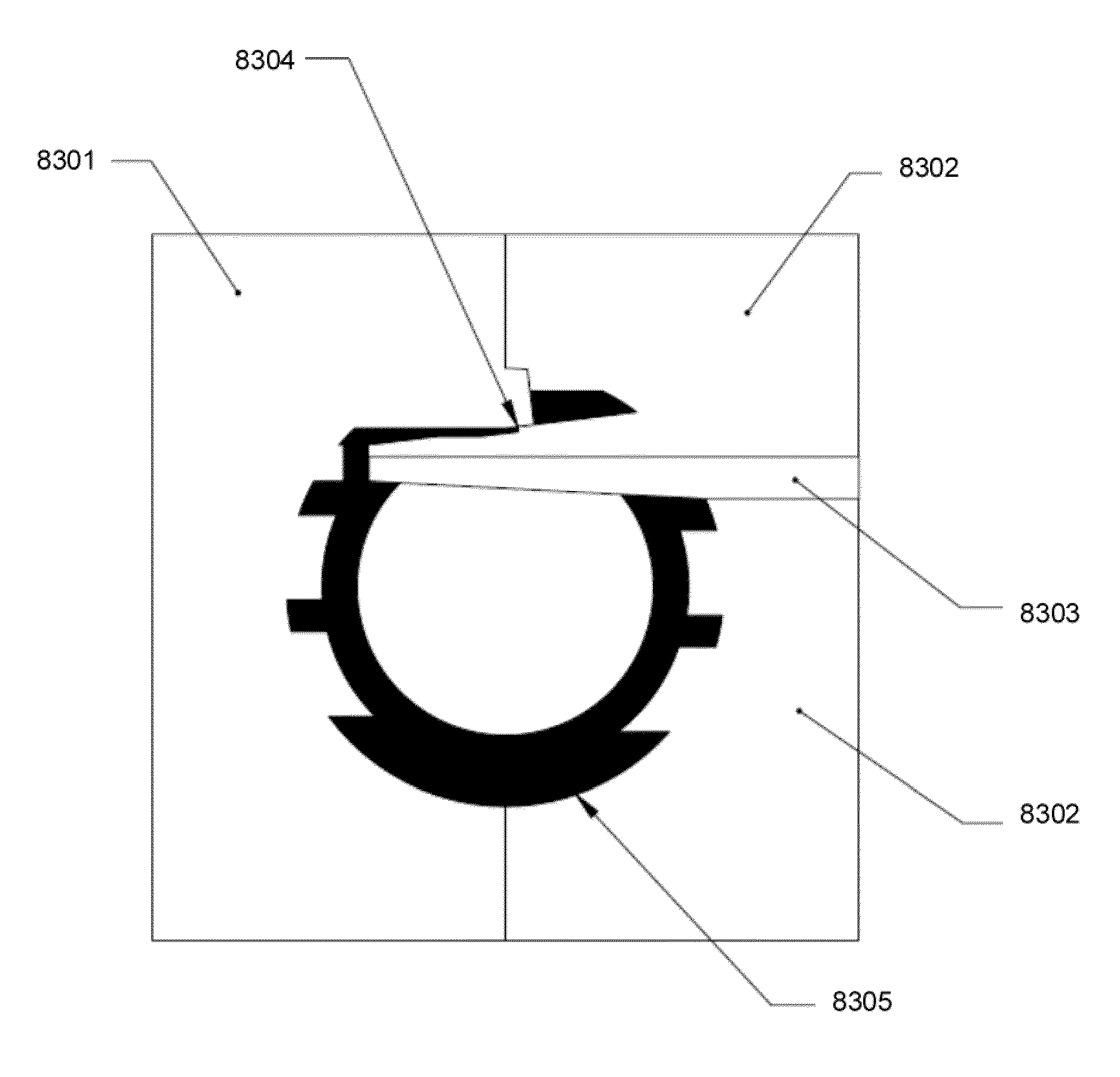
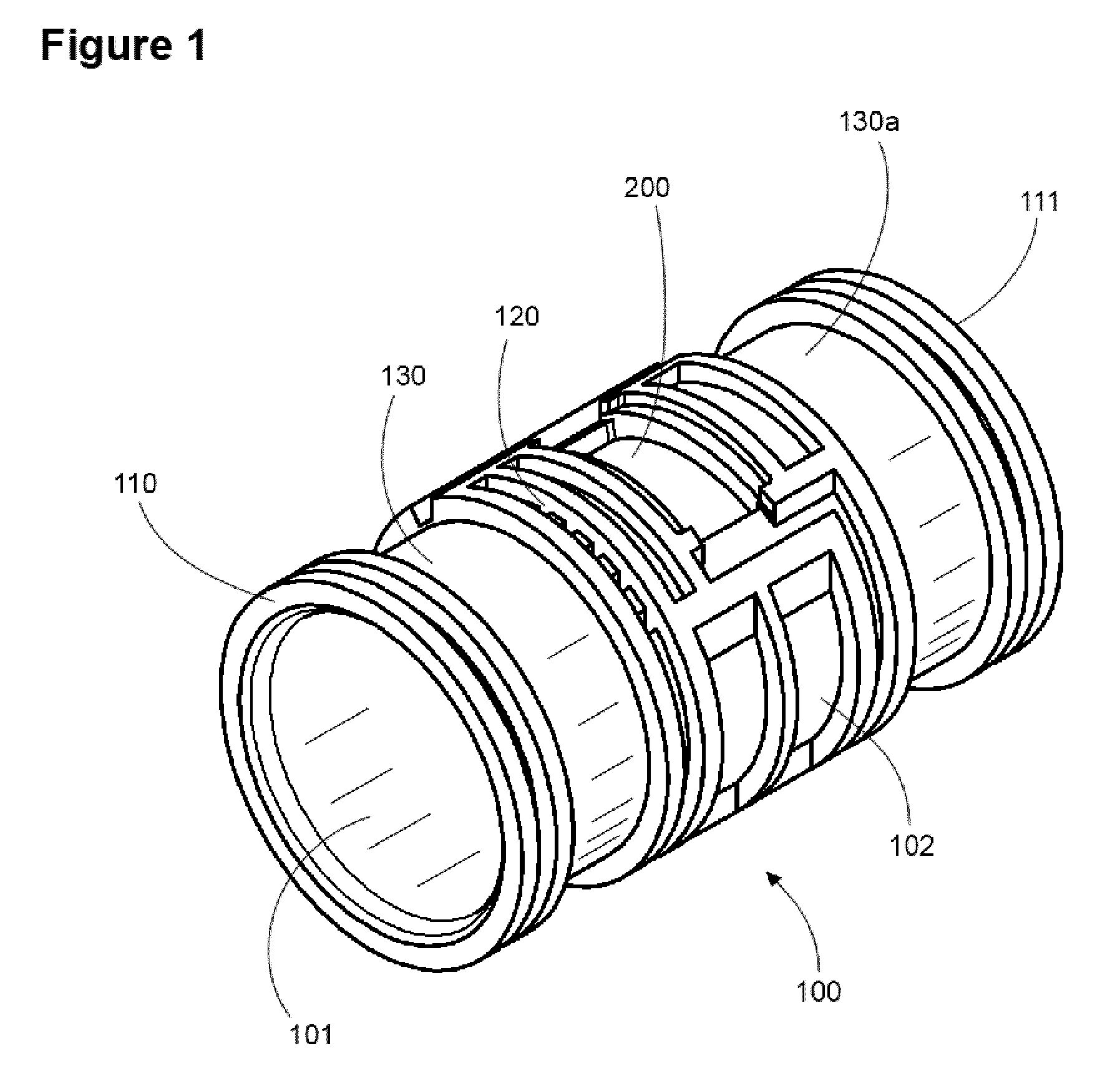
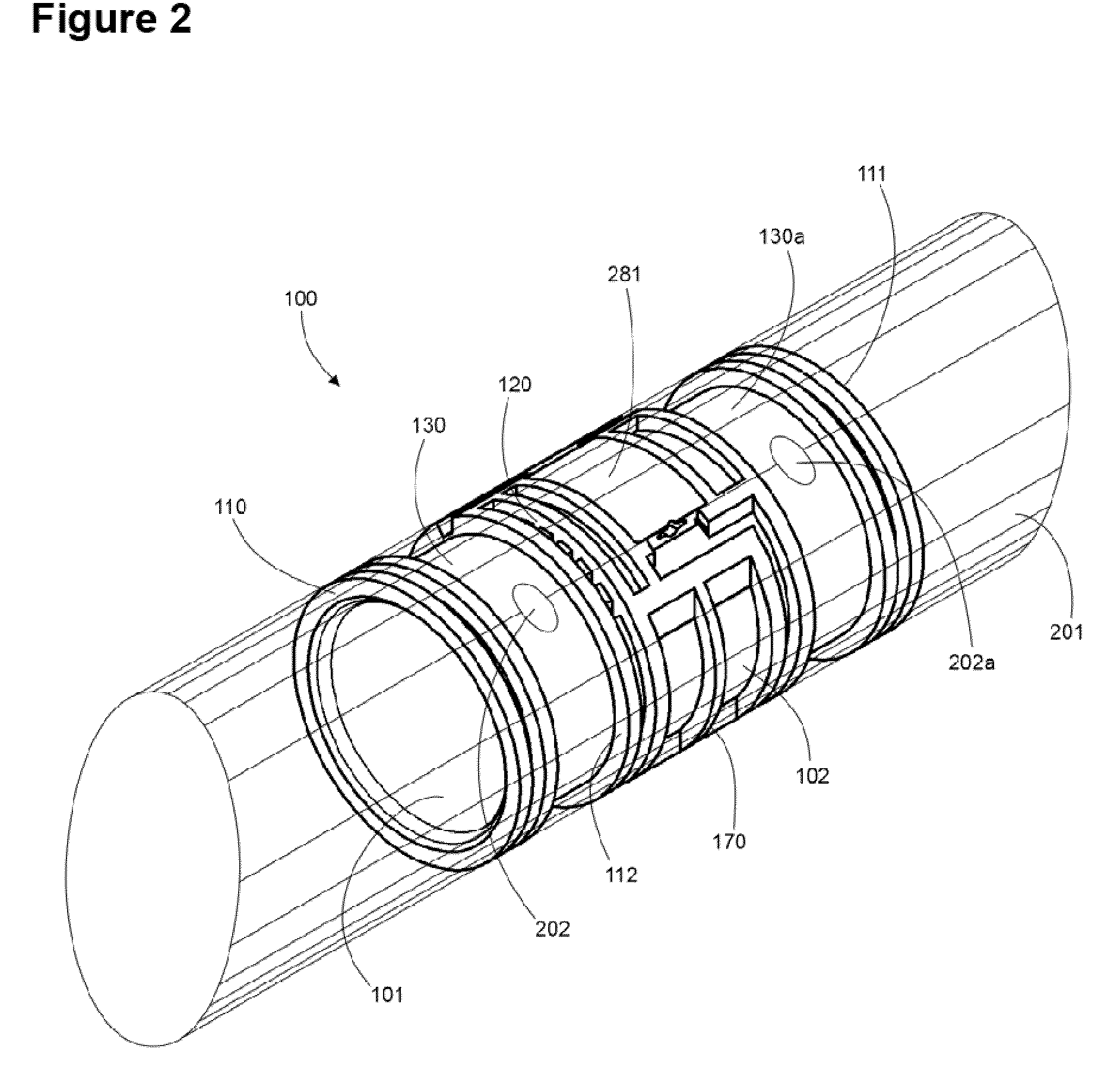
[0178]Embodiments include an emitter body having inner surface 101, outer surface 102 (see FIG. 68) that forms the floor of the emitter working elements, first end 110 and second end 111. The drip emitter also includes an outer portion which refers to the portion that contacts an enclosing pipe and an inner portion that is utilized herein to signify anything beneath the floor of the outer surface 102. The emitter of FIG. 65 is inserted into a pipe or hose as is shown (with respect to the first embodiment) as a shaded tube in FIG. 2 wherein holes are created in the hose to allow water flowing from the inside of the pipe, and hence inside of inner surface 101 through inlet or filter 120 (wherein the inlet may be utilized as a placeholder for a fluid retainment valve for example), through labyrinth 140, to pressure compensating chamber 6510 (shown as the empty volume above the deformable element 6501 that is enclosed by an enclosing pipe), to pressure compensating chamber exit 6502 and...


PUM

PropertyMeasurementUnit
pressureaaaaaaaaaa
inner diameteraaaaaaaaaa
heightaaaaaaaaaa

Abstract

Drip emitter having a pressure compensating element that does not contact the enclosing pipe. First known drip emitter formed from a two-shot injection mold process that includes a deformable element, membrane, compressible element or pressure compensating element that compensates pressure or flow of water against a stiff injection molded surface that is part of the drip emitter body. In addition, this is the first drip emitter (two-shot or otherwise) that includes a compensating surface that is not parallel to the membrane, i.e., at an angle to the plane of the pressure compensating element. May include fluid retainment valve, ventable / anti-siphon / non-drain or other, as part of second injection with second or third material. Allows for simple injection mold construction and eliminates need for ISO conditioning to properly seat the membrane before testing.

Description

[0001]This application is a continuation in part of U.S. patent application Ser. No. 12 / 434,565 filed 1 May 2009 now U.S. Pat. No. 8,372,326, which is a continuation in part of U.S. patent application Ser. No. 12 / 254,761 filed 20 Oct. 2008 now U.S. Pat. No. 7,988,076, the specifications of which are all hereby incorporated herein by reference.BACKGROUND OF THE INVENTION[0002]1. Field of the Invention[0003]Embodiments of the invention described herein pertain to the field of irrigation apparatus. More particularly, but not by way of limitation, one or more embodiments of the invention enable an internally pressure compensated non-clogging drip emitter.[0004]2. Description of the Related Art[0005]There are multiple types of irrigation drippers. Simple drippers exist that are inserted serially along pipe, either by forcing a hole into the pipe and placing the dripper on the outside of the pipe, or by cutting the pipe and inserting the dripper in line with the pipe. These systems requir...

Claims


Application Information

Patent Timeline
Patent Type & Authority Patents(United States)
IPC IPC(8): B29C45/14
CPCB29C45/1635B29C45/1676
Inventor MAMO, SHAY
Owner MAMO SHAY
Why Eureka
Try Eureka