Control Method

Inactive Publication Date: 2009-11-05
ABB RES LTD
View PDF23 Cites 17 Cited by
  • Summary
  • Abstract
  • Description
  • Claims
  • Application Information

AI Technical Summary

Benefits of technology

[0007]It is an object of the present invention to provide a wind turbine for which said problems arising when low power conditions prevail have been substantial

Problems solved by technology

Thus, the period of times between a need of repair of components of the drive train arises may be substantially prolonged, which involves a considerable saving of costs, especially in labour and as a consequence of reduced losses during time periods of repai

Method used


Image

  • Control Method
  • Control Method

Examples


Example

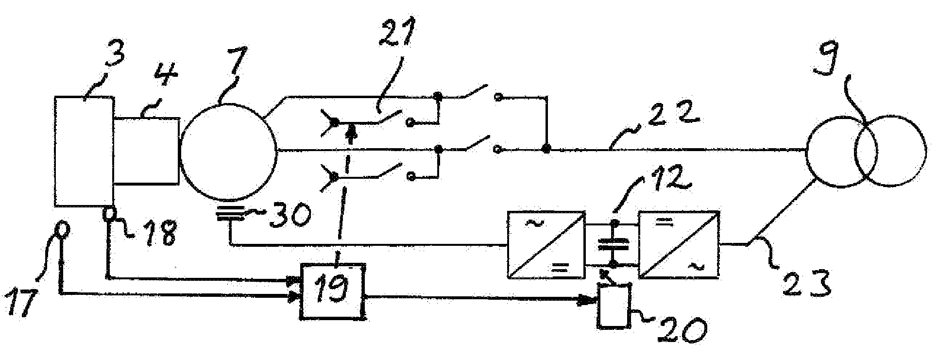
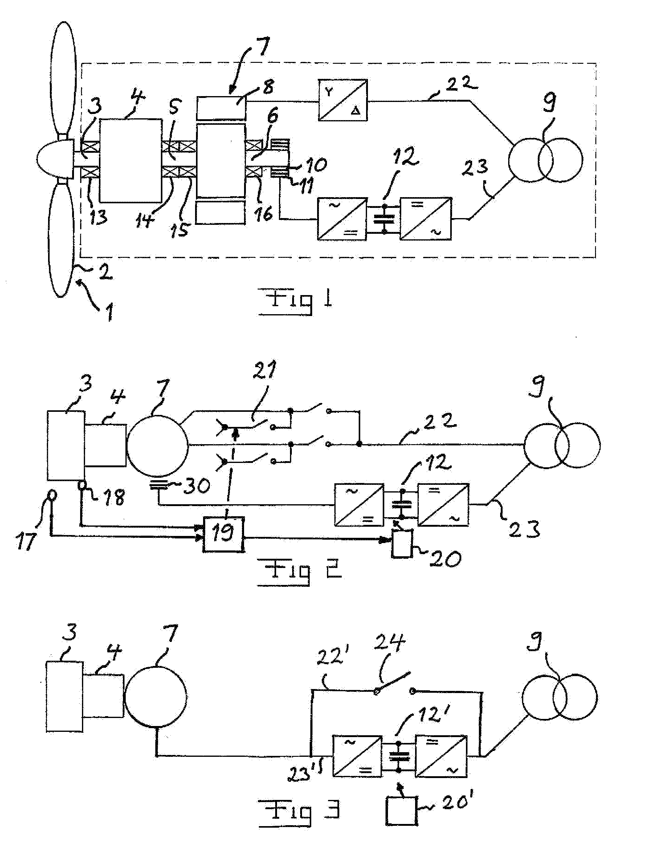
[0025]FIG. 1 illustrates very schematically the general construction of a wind turbine known as a wind turbine having a Double-Fed Induction Generator (DFIG). The part of the wind turbine within the frame of dashed lines is normally arranged in the so-called nacelle or house arranged on the column of a wind power station. The wind turbine has a propeller 1 with blades 2 arranged to catch the wind and drive a wind rotor 3 to rotate. The wind rotor has normally a rotation speed of 3-15 rpm and 5-20 rpm for a wind turbine with a rating of 3 MW and 2 MW, respectively. The wind rotor 3 is connected to a gearbox 4 normally increasing the rotational speed on an output shaft 5 thereof to be 100 times the rotational speed of the wind rotor 3 for the higher rating and 60 times for the lower rating. The output shaft 5 is connected to or carries a rotor 6 of an asynchronous generator 7 having the stator windings 8 thereof through a first branch 22 connected to an electric power transmission net...


PUM


Abstract

A generator of a wind turbine is at low power conditions operated as a motor by control of a frequency converter to feed electric power from an electric power transmission network to the generator for raising the speed of the wind rotor above a predetermined level for lubricating rotating parts of a drive train of the wind turbine.

Description

CROSS-REFERENCE TO RELATED APPLICATIONS[0001]The present application is a continuation of pending International patent application PCT / SE2006 / 001107 filed on Sep. 29, 2006 which designates the United States, the content of which is incorporated herein by reference.FIELD OF THE INVENTION[0002]The present relates to a wind turbine comprising a drive train with a wind rotor connected to a generator rotor through a gear box and having bearings for journalling rotating parts of the drive train, said generator being adapted to be connected to an electric power transmission network.BACKGROUND OF THE INVENTION[0003]Accordingly, “wind turbine” is in this disclosure defined to include a wind rotor with turbine blades, gearbox, generator and associated equipment as well as equipment used for feeding electric power from the generator to said electric power transmission network or a transformer connected thereto.[0004]The generator in said wind turbine may be of any known type, such as an asynch...

Claims


Application Information

Patent Timeline
IPC IPC(8): H02P9/04
CPCF03D9/002F03D11/0008F05B2240/20F05B2270/101F05B2270/1095F03D7/026F05B2270/327Y02E10/722Y02E10/723Y02E10/725F05B2270/32F03D9/25F03D80/70Y02E10/72
Inventor GERTMAR, LARSWRAAE, LEIF-ERIKWRAAE, HELLECHRISTENSEN, HANS C.MANTERE, JUHANIKOLDBY, ERIK
Owner ABB RES LTD
Why Eureka
Try Eureka