Pyrolysis systems

a technology of pyrolysis systems and pyrolysis equipment, which is applied in the direction of combustion types, machines/engines, lighting and heating apparatuses, etc., can solve the problems of increasing disposal problems of waste materials, wastes are generally abandoned, and refuse and toxic waste are often burned, so as to reduce the discharge of flue gas, enhance the viability of use, and increase the energy yield

Inactive Publication Date: 2018-10-11
REED FRANK
View PDF2 Cites 0 Cited by
  • Summary
  • Abstract
  • Description
  • Claims
  • Application Information

AI Technical Summary

Benefits of technology

[0007]The present disclosure features improved pyrolysis units for use in pyrolysis systems that include a pyrolysis unit, a thermal oxidizer unit, and a stack unit, e.g., of the type described in U.S. Pat. No. 6,758,150. As discussed above, in the pyrolysis systems disclosed herein, syngas is exhausted from the pyrolysis unit in a manner that prevents formation of clinkers in the exhaust duct, and flue gases are discharged from the pyrolysis unit in a manner that recovers their heat and eliminates discharge of flue gas to the environment. These and other features of the pyrolysis units enhances their viability for use in commercial processes and may increase energy yield from pyrolysis systems including the pyrolysis units.

Problems solved by technology

Waste materials present ever-increasing disposal problems.
In the past, refuse and toxic waste were often burned.
However, due to increased governmental and regulatory standards, the potential public health impacts of carcinogenic air emissions, such as dioxins and furans, and the risks of spreading toxic plumes, the burning of wastes has generally been abandoned.

Method used


Image

  • Pyrolysis systems
  • Pyrolysis systems
  • Pyrolysis systems

Examples


Embodiment Construction

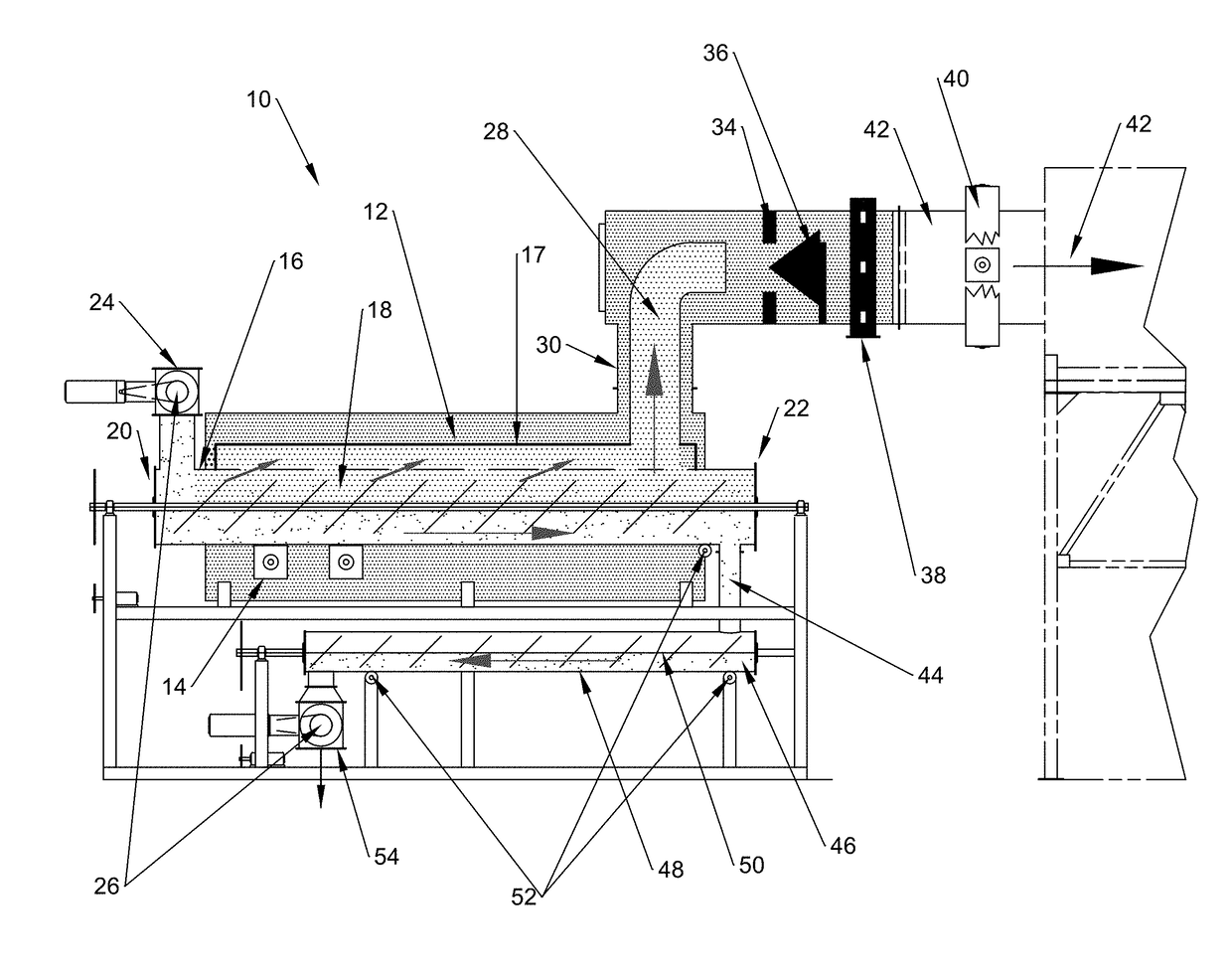
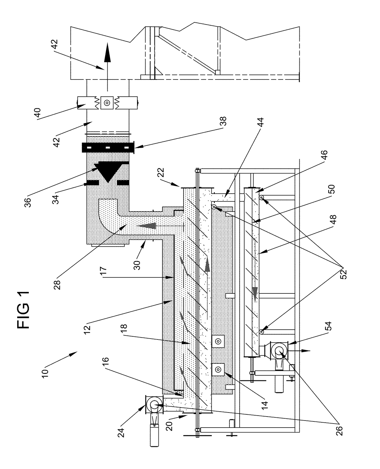
[0020]A pyrolysis unit 10 is shown in FIG. 1. Pyrolysis unit 10 may be used to perform the initial pyrolysis step in a pyrolysis system that includes a thermal oxidizer unit and stack unit (not shown.) As noted above, the pyrolysis unit routes syngas discharge in a manner that reduces maintenance of the unit, routes flue gases in a manner that recovers their heat and eliminates discharge of flue gas to the environment, and includes other features which enhance the commercial viability of the pyrolysis system.

[0021]The pyrolysis unit 10 includes a combustion chamber 12, which is made from materials capable of withstanding temperatures of 1200-2600° F. Burners 14 are positioned within the combustion chamber. These burners may be natural gas or propane-fired and are adapted to generate and supply hot combustion gases into the combustion chamber. While two burners are illustrated, more or fewer could be provided.

[0022]A main retort 16 is disposed within the combustion chamber 12. Pyroly...


PUM

PropertyMeasurementUnit
temperaturesaaaaaaaaaa
temperatureaaaaaaaaaa

Abstract

Systems and methods are disclosed for pyrolysis of waste feed material. Some systems include a main retort and a secondary retort. Syngas is produced by pyrolysis in the main retort, and is then mixed with combustion air and ignited, in some cases to produce energy. Carbon char travels to the secondary retort and is exhausted from the system through an airlock.

Description

RELATED APPLICATION[0001]This application is a continuation application of U.S. application Ser. No. 15 / 365,633, filed Nov. 30, 2016, which is a continuation application of U.S. application Ser. No. 15 / 196,645, filed Jun. 29, 2016, now U.S. Pat. No. 9,534,175, granted on Jan. 3, 2017, which is a continuation application of U.S. application Ser. No. 14 / 105,832, filed Dec. 13, 2013, now U.S. Pat. No. 9,394,484, granted on Jul. 19, 2016, the entire contents of which are hereby incorporated by reference.FIELD OF INVENTION[0002]The present invention relates to systems and methods for pyrolyzing waste materials and recovering heat from the pyrolysis process.BACKGROUND[0003]Waste materials present ever-increasing disposal problems.[0004]In the past, refuse and toxic waste were often burned. However, due to increased governmental and regulatory standards, the potential public health impacts of carcinogenic air emissions, such as dioxins and furans, and the risks of spreading toxic plumes, t...

Claims


Application Information

Patent Timeline
Patent Type & Authority Applications(United States)
IPC IPC(8): C10B53/07F01K5/02C01B3/02F23J1/06F23G7/12F23G5/027C10B47/44C10K3/06C10B27/06C10B7/10C10B21/12
CPCF01K5/02C01B3/02Y02P20/143F23G2209/281F23G2203/8013F23G2201/303F23G2201/301F23J1/06F23G7/12F23G5/0276C10B53/07C10B47/44C10K3/06C10B27/06C10B7/10C10B21/12
Inventor REED, FRANK
Owner REED FRANK
Why Eureka
Try Eureka