Plasma assisted gasification system with agitator drive assembly in reactor vessel

a technology of gasification system and agitator, which is applied in the field of gasification systems, can solve the problems of limiting the locale in which the conventional gasification system may be constructed efficiently, the cost of constructing and operating the conventional gasification system in remote locales often outweighs the benefit of power generated, and achieves the effect of convenient system transportation and convenient shipmen

Inactive Publication Date: 2012-05-17
ADAPTIVEARC
View PDF7 Cites 6 Cited by
  • Summary
  • Abstract
  • Description
  • Claims
  • Application Information

AI Technical Summary

Benefits of technology

[0005]A plasma assisted gasification system having a controlled zone gasification reactor is disclosed for converting fuel, such as, but not limited to, biomass, to electricity. The gasification system can create electricity from biomass by producing syngas to replace the need for petroleum based fuels to engines, such as, but not limited to, diesel engines and turbine engines. The engines may operate at least partially on the syngas supplied by the syngas separation chamber

Problems solved by technology

A challenging aspect of using gasification systems for power generation from waste fuel sources is efficiently producing power while handling the waste products developed within the systems.
Gasification systems used for power generation systems typically have a large footprint, such as an acre or more, and are typically constructed on-site.
As such,

Method used


Image

  • Plasma assisted gasification system with agitator drive assembly in reactor vessel
  • Plasma assisted gasification system with agitator drive assembly in reactor vessel
  • Plasma assisted gasification system with agitator drive assembly in reactor vessel

Examples


Embodiment Construction

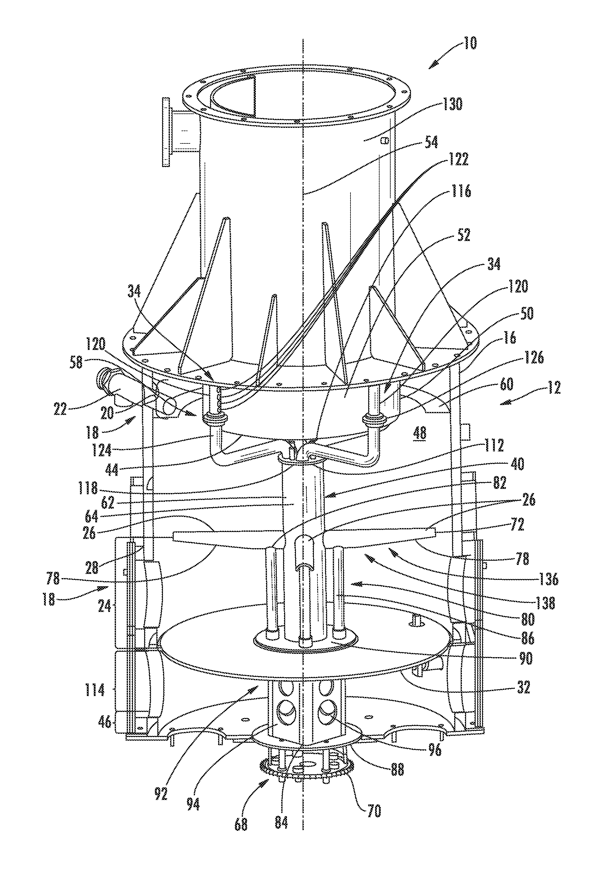
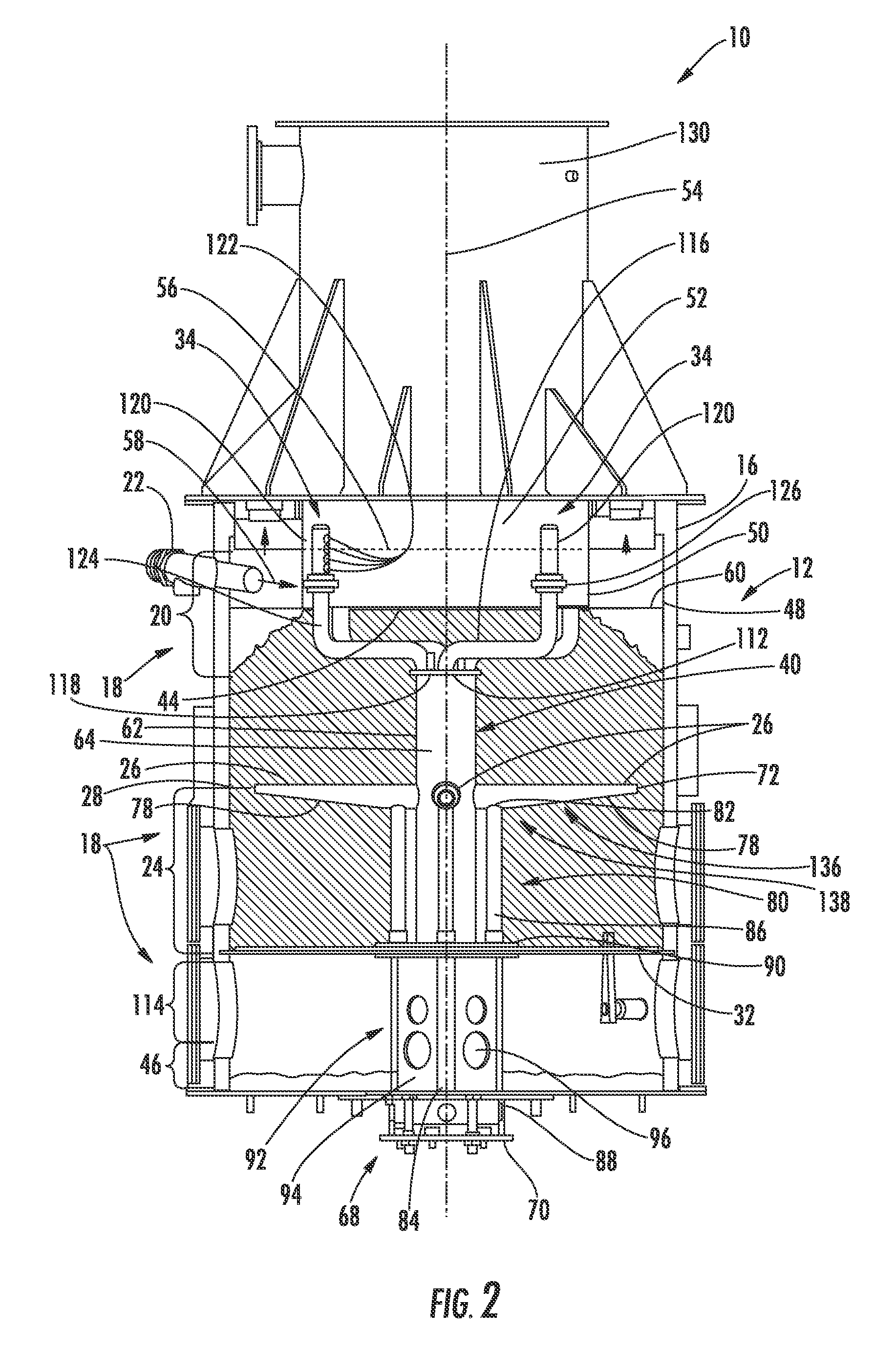
[0032]Aspects of the present invention relate to gasification components, systems and associated methods that can enhance the performance of a plasma assisted gasification system. Embodiments according to aspects of the invention are shown in FIGS. 1-10, but the present invention is not limited to the illustrated structure or application. Rather, the following detailed description is intended only as exemplary.

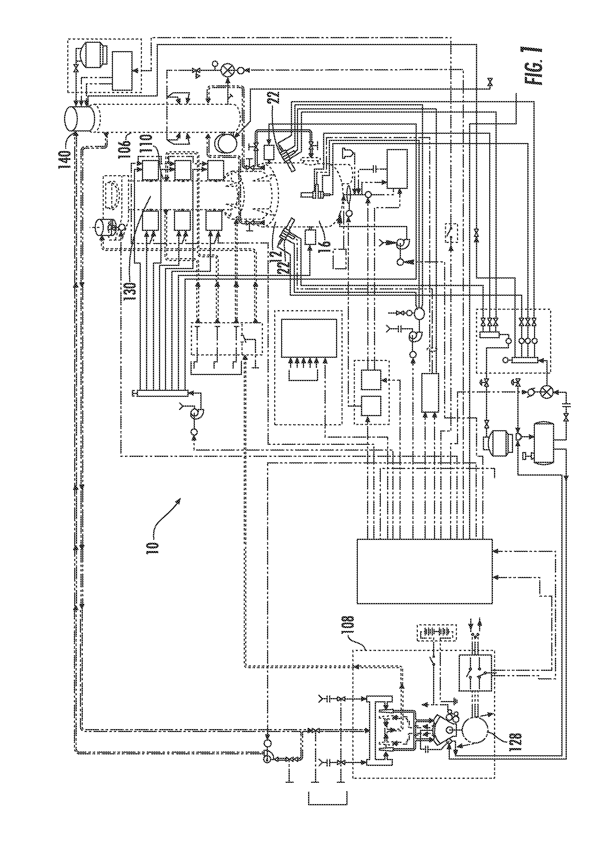
[0033]As shown in FIGS. 1-10, a plasma assisted gasification system 10 having a controlled zone gasification reactor 12 is disclosed for converting fuel 142, such as, but not limited to, biomass, to electricity. The gasification system 10 can create electricity from biomass by producing syngas to replace the need for petroleum based fuels to engines, such as, but not limited to, diesel engines and turbine engines 108. The engines 108, as shown in FIGS. 1, 9 and 10, may operate at least partially on the syngas supplied by the syngas separation chamber. The gasification system 1...


PUM


Abstract

A controlled zone gasification reactor with an agitator drive assembly for a plasma assisted gasification reaction system is disclosed for converting fuel, such as, but not limited to, biomass, to syngas to replace petroleum based fuels used in power generation. The agitator drive assembly that prevents formation of burn channels with in the fuel. The agitator drive assembly may include a syngas separation chamber configured to produce clean syngas, thereby requiring less filtering. The syngas separation chamber may feed syngas downstream to a syngas heater in a pyrolysis reaction zone in the reactor vessel.

Description

FIELD OF THE INVENTION[0001]The invention relates in general to gasification systems and, more particularly, to gasification systems capable of using waste products as fuel to form clean synthetic gas (syngas) that is useful for power generation.BACKGROUND OF THE INVENTION[0002]Gasification systems have been used for power generation by converting biomass fuel sources into combustible gases that contain nearly all of the energy of the biomass. The gasification systems convert carbonaceous materials, such as coal, biomass, biofuel, carbon dioxide, hydrogen and petroluem, into charcoal, wood-oils, and tars using both combustion and pyrolysis with a controlled amount of oxygen or steam. The gasification systems produce syngas, which is used as a fuel within engines, such as internal combustion engines and turbine engines. Syngas may be combusted at higher temperatures than other fuels courses, thereby making internal combustion of syngas potentially more efficient than other fuel sourc...

Claims


Application Information

Patent Timeline
IPC IPC(8): C10J3/72
CPCY02E50/32F02B43/08C10J3/18C10J2300/0909C10J3/20C10J2300/1606C10J2300/165C10J2300/1671C10J2300/1238Y02E50/30Y02T10/30Y02P20/129
Inventor JUVAN, CHRISTIAN H. A.
Owner ADAPTIVEARC
Why Eureka
Try Eureka