Steel bar cutter

A cutting machine, steel bar technology, applied in other manufacturing equipment/tools, manufacturing tools, etc., can solve the problems of uncertain work efficiency, cutting machine is not equipped with automatic feeding equipment, etc., to achieve high work efficiency, fast cutting speed, The effect of reducing production costs

Active Publication Date: 2011-01-19
NINGBO YONGXIN STEEL TUBE
View PDF7 Cites 9 Cited by
  • Summary
  • Abstract
  • Description
  • Claims
  • Application Information

AI Technical Summary

Problems solved by technology

The cutting machine uses the downward shearing force of the heavy-duty hydraulic device to cut the steel, but the cutting machine is not equipped with automatic feeding equipment, and there is no fixing device for the broken steel. When cutting, the sheared steel rod may roll out of the cutting hole because it is...

Method used


Image

  • Steel bar cutter
  • Steel bar cutter
  • Steel bar cutter

Examples


Embodiment Construction

[0032] The present invention will be further described below in conjunction with accompanying drawing and specific embodiment:

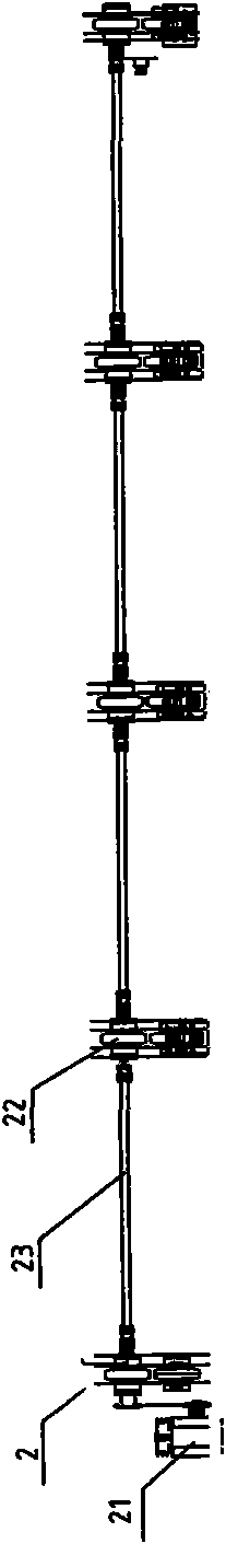
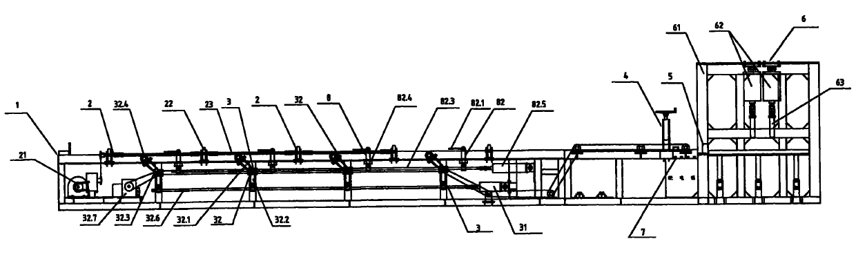
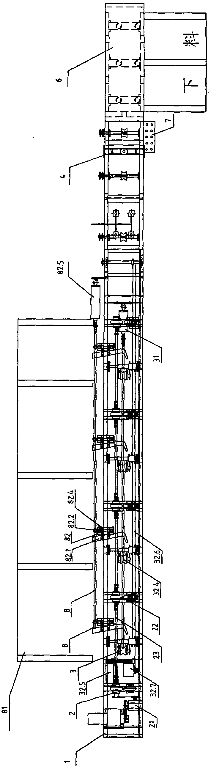
[0033] figure 1 with figure 2 As shown, the steel bar cutting machine of the present invention includes a frame 1, a power mechanism, and also includes a circumferential rotation device 2, a longitudinal feeding device 3, a pressing device 4, a lifting fulcrum 5, a stamping device 6, and an operation console 7 And a cutting device arranged outside the frame.

[0034] Frame 1 is a cuboid frame, the front section of frame 1 is a pretreatment area, and the rear section is a pressing area, and the table top of the pretreatment area is lower than the table top of the pressing area;

[0035]The power mechanism includes motor I 21, motor II 32.5, transmission cylinder I 31, cylinder II 82.5 and stamping cylinder 62;

[0036] image 3 As shown, the circumferential rotation device 2 refers to a device that makes the steel bar rotate circumferentially, an...


PUM


Abstract

The invention discloses a steel bar cutter, which comprises a machine frame (1), a power mechanism, a circumferential rotating device (2), a longitudinal feeding device (3), a pressing device (4), an ejecting fulcrum (5), a punching device (6), an operating console (7) and a cutting device arranged outside the machine frame, wherein a motor I in the circumferential rotating device (2) drives a plurality of rotating carrier rolls consisting of driving wheels and driven wheels in pair to rotate; a steel bar rotates with the rotating carrier rolls; the cutting device arranged outside the machineframe cuts a circle of cut mark mouth on the steel bar; the longitudinal feeding device (3) feeds the steel bar to the rear table top of the machine frame (1); the punching device (6) punches the steel bar suspended behind the ejecting fulcrum (5); and the steel bar is cut off suddenly at the cut much mouth. The steel bar cutter has the advantages of steam line operation, continuous feeding, mechanical conveying, high cutting speed, high working efficiency, simple operation, time and labor conservation and production cost reduction.

Description

Technical field: [0001] The invention relates to a steel bar cutting device, in particular to large-caliber steel bar cutting equipment, specifically a steel bar cutting machine. Background technique: [0002] The cutting of steel bars or steel bars is a routine thing in industrial production. It is relatively easy to cut small-diameter steel bars with steel shears, but for large-diameter steel bars, grinding wheels are often used for cutting. , This cutting method produces a lot of noise, a lot of dust, a large loss of the grinding wheel, and low cutting efficiency. In order to change this backward cutting method, some people have designed more advanced cutting equipment, such as: the National Patent Office disclosed the invention named "Hydraulic Heavy Swing Double Side Cutting Machine" on December 3, 2008 with the authorized announcement number CN20115793Y Patent, the technical solution disclosed in the patent application document is: a hydraulic heavy-duty swing double-...

Claims


Application Information

Patent Timeline
IPC IPC(8): B23P23/02
Inventor 胡方法
Owner NINGBO YONGXIN STEEL TUBE
Why Eureka
Try Eureka