Tool for cutting off packaged flat steel and manufacturing method

A technology for cutting packaging and manufacturing methods, which is applied in the direction of shearing devices, manufacturing tools, metal processing equipment, etc., can solve the problems of finger injury, time-consuming and laborious, small gap between packaging flat steel and section steel, etc., and achieves simple and convenient use of tools and improved The effect of work efficiency and simple tool structure

Inactive Publication Date: 2018-09-21
MCC5 GROUP CORP SHANGHAI
View PDF4 Cites 0 Cited by
  • Summary
  • Abstract
  • Description
  • Claims
  • Application Information

AI Technical Summary

Problems solved by technology

However, the gap between some packaged flat steel and section steel is small, and it is extremely inconvenient to remove with pliers, time-consuming and laborious, and even cause finger injuries
[0003] Therefore known vise cuts flat steel and removes packaging mode and there is above-mentioned inconvenience and problem

Method used


Image

  • Tool for cutting off packaged flat steel and manufacturing method

Examples


Embodiment 1

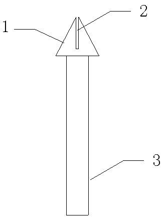
[0032] The tool for cutting packaging flat steel of the present invention includes a cutting head and a handle.

[0033] see now figure 1 , figure 1 It is a structural schematic diagram of a tool for cutting packaging flat steel according to an embodiment of the present invention. As shown in the figure, the cutting head is an isosceles triangle with a height of 60 mm and a base length of 40 mm. The material of the cutting head of the triangle is a steel plate with a thickness of 20 mm.

[0034] The handle is a steel pipe 3, the steel pipe material is DN32, and the length of the steel pipe is 1.5m.

[0035] Wherein: the center point of the bottom edge of the triangular cutting head 1 is welded and fixed to one end of the steel pipe, and the top of the corner corresponding to the bottom edge is provided with a groove 2 with a depth of 40mm, and the center line of the groove is on the same straight line as the axis of the steel pipe.

Embodiment 2

[0037] The manufacturing method of the tool that is used to cut off packing flat steel of the present invention, comprises the following steps:

[0038] a. Use a 20mm thick steel plate to make a triangle with a width of 40mm and a height of 60mm;

[0039] b. A groove with a width of 20mm is opened in the middle of the triangle, and the depth of the groove is 40mm, which is used as the cone head;

[0040] c. The bottom of the cone head is welded and fixed to the steel pipe of DN32, the steel pipe is 600mm long, and the tool for cutting the flat steel for packaging is completed.

Embodiment 3

[0042] The method of using the tool for cutting the packaged flat steel of the present invention: when cutting the packaged flat steel, make the triangular cutting head perpendicular to the flat steel, all the grooves go deep into the flat steel, lift the steel pipe upwards, and the packaged flat steel is quickly cut off.

[0043] The present invention has substantive features and significant technological progress. The tool and manufacturing method for cutting flat steel for packaging in the present invention has simple structure, convenient manufacture, and is convenient to carry. It can cut flat steel simply and quickly, save manpower and time, and improve work efficiency.


PUM

PropertyMeasurementUnit
lengthaaaaaaaaaa
depthaaaaaaaaaa
thicknessaaaaaaaaaa

Abstract

The invention provides a tool for cutting off packaged flat steel. The tool comprises a cut-off head and a handle and is characterized in that the cut-off head is triangular; the triangular cut-off head is made from a steel plate; the handle is a steel pipe (3), wherein the center point of the bottom edge of the triangular cut-off head (1) and one end of the steel pipe are fixed in a welding manner; the top end of a corner corresponding to the bottom edge is provided with a groove (2); and the center line of the groove and the axis of the steel pipe are in the same straight line. The tool forcutting off the packaged flat steel and the manufacturing method provided by the invention have the advantages that the tool is simple in structure and convenient to manufacture, the application method is simple and convenient, the tool can be used for quickly cutting off the flat steel, time and efforts are saved, and the work efficiency is improved.

Description

technical field [0001] The invention relates to a tool for dismantling flat steel for packaging materials such as rails, H-shaped steel, and I-beam on a construction site, in particular to a tool for cutting flat steel for packaging and a manufacturing method. Background technique [0002] Steel rails, H-shaped steel, I-beam, channel steel, angle steel, galvanized I-beam, galvanized channel steel, galvanized angle steel, square steel, hexagonal steel, octagonal steel, flat steel and other small steel for general construction sites, Usually framed bundled packaging. Generally, 40mm×4mm flat steel with large curvature is used for bundling, and this kind of packaging flat steel is fixed on the section steel by a strapping machine. After the construction site receives this kind of frame-type bundle package packed with flat steel, it generally uses vise to cut off the flat steel and remove the package. However, the gap between part of the packaged flat steel and the section ste...

Claims


Application Information

Patent Timeline
Patent Type & Authority Applications(China)
IPC IPC(8): B23D29/02
CPCB23D29/02
Inventor 张允升李先南梁广远汪从刘宗宝
Owner MCC5 GROUP CORP SHANGHAI
Why Eureka
Try Eureka