An automatic laminating device for medical trays

A laminating device and automatic technology, applied in the directions of packaging material feeding device, packaging, transportation and packaging, etc., can solve the problems of unsightly appearance, many people, inclination, etc., and achieve the effect of large volume and manpower saving.

Active Publication Date: 2021-10-22
SHANGDONG ZHONGBAOKANG MEDICAL DEVICES
View PDF6 Cites 0 Cited by
  • Summary
  • Abstract
  • Description
  • Claims
  • Application Information

AI Technical Summary

Problems solved by technology

[0008] In order to overcome the problems of inclination, irregularity and unsightly appearance when cutting the membrane manually, the present invention will easily cause manual fatigue due to large-scale work, and long-term lowering of the head to cut off the membrane will easily lead to symptoms such as cervical spondylosis and periarthritis of the shoulder, and more personnel are used, which is time-consuming The shortcoming of laboriousness, the technical problem to be solved in the present invention is to provide a kind of medical tray automatic lamination device that can automatically cover the medical tray

Method used


Image

  • An automatic laminating device for medical trays
  • An automatic laminating device for medical trays
  • An automatic laminating device for medical trays

Examples


Embodiment 1

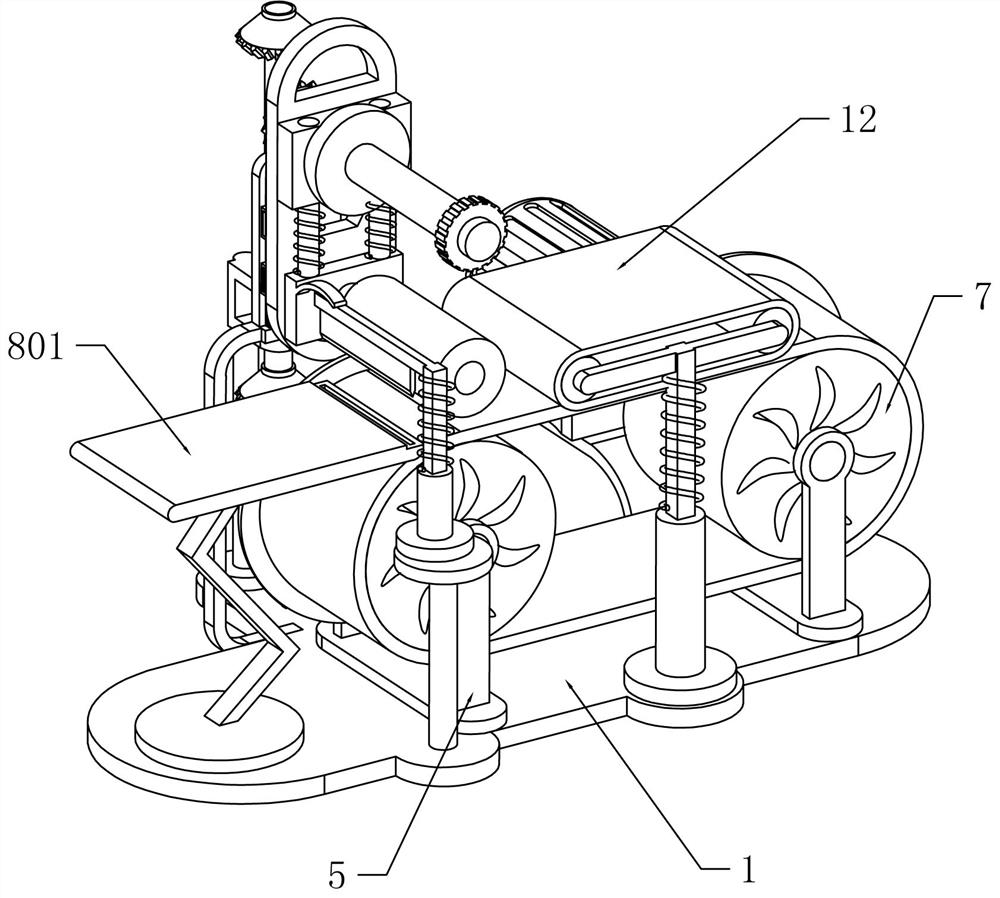
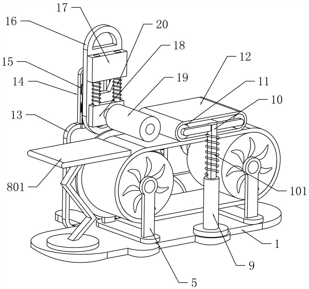
[0065] An automatic film covering device for medical trays, such as Figure 1-5 As shown, it includes a bottom plate 1, a motor base 2, a servo motor 3, a coupling 4, a conveyor belt assembly, a transition assembly, and a pressing assembly. On the seat 2, the coupling 4 is fixed to the output shaft of the servo motor 3, the conveyor belt assembly is fixed on the top of the bottom plate 1, the conveyor belt assembly is connected to the coupling 4 and is located in front of the motor seat 2, and the transition assembly is fixed on the bottom plate 1. On the top of the conveyor belt assembly, the pressing assembly is fixed on the bottom plate 1 and connected with the conveyor belt assembly.

[0066] When laminating the medical tray, manually put the medical tray on the conveyor belt assembly, start the servo motor 3, the servo motor 3 drives the conveyor belt assembly to run, the medical tray moves from right to left along the conveyor belt assembly, and the medical tray transiti...

Embodiment 2

[0068] On the basis of Example 1, such as Figure 1-3As shown, the conveyor belt assembly includes a support frame 5, a rotating shaft 6, a transmission wheel 7, a conveyor belt 8, and a support plate 801. There are two U-shaped support frames 5, which are respectively fixed on the upper left and right positions of the bottom plate 1, and the right side supports The rear side of the frame 5 is opposite to the shaft coupling 4, and the rotating shaft 6 is two rotating shafts connected to the support frame 5 on the left and right sides respectively. A transmission wheel 7 is socketed, and two transmission wheels 7 are arranged in the support frame 5 respectively. The conveyor belt 8 bypasses the two transmission wheels 7 .

[0069] When the servo motor 3 is started to rotate, the shaft coupling 4 drives the rotating shaft 6 to rotate, and the transmission wheel 7 drives the conveyor belt 8 to start transmission, so that the conveyor belt 8 drives another transmission wheel 7 to ...

Embodiment 3

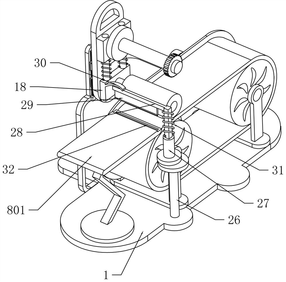
[0076] On the basis of Example 2, such as Figure 4-5 As shown, it also includes a stop rod 21, a rotating rod 22, a helical gear 23, a connecting rod 24 and a tightening nut 25. The stop rod 21 is affixed to the upper rear side of the base plate 1, and the rotation rod 22 is rotatably connected to the stop rod 21 upper part, the helical gear 23 is two groups, one of the first group of helical gears 23 is fixed on the upper end of the rotating rod 22, one of the second group of helical gears 23 is fixed on the lower end of the rotating rod 22, and the other helical gear 23 of the second group is fixed on the lower end of the rotating rod 22. The gear 23 is fixedly connected to the rear side of the left rotating shaft 6, the connecting rod 24 is connected to the sliding sleeve plate 17 in rotation, another helical gear 23 of the first group is fixedly connected to the rear end of the connecting rod 24, and the nut 25 and the connecting rod 24 are tightened before external threa...


PUM


Abstract

The invention relates to a film covering device, in particular to an automatic film covering device for medical trays. The technical problem to be solved by the present invention is to provide an automatic film coating device for medical trays that can automatically cover the medical trays. In order to solve the above-mentioned technical problems, the present invention provides such an automatic film covering device for medical trays, which includes: a base plate; a motor base, fixed to one side of the base plate; a servo motor, fixed to the motor base; Connected to the output shaft of the servo motor; the conveyor belt component is fixed to the bottom plate and connected with the coupling, and is located on one side of the motor seat; the transition component is fixed to the bottom plate and close to the conveyor belt component; the compression component is fixed to the bottom plate and is connected with the Conveyor belt assembly connections. The invention has a large volume and is suitable for lamination in large quantities. The medical tray and the lamination can be fast bonded through the conveyor belt assembly and the transition assembly, replacing the function of manual lamination.

Description

technical field [0001] The invention relates to a film covering device, in particular to an automatic film covering device for medical trays. Background technique [0002] Laminating process With the continuous improvement of customers' requirements for printing and packaging products and people's understanding and recognition of film-coated products, the film-coating process is more and more widely used in various fields of life and production. If you pay attention, you will soon find a wide variety of coated products, such as pictures, color pages, publications, cartons, cartons, photos, etc., too numerous to mention. [0003] Lamination can protect printed products from wear and tear, make printed products brighter and fuller in color, increase printed product strength (such as puncture strength, tensile strength), and prolong the storage time of printed products (such as photos that do not fade or yellow after plastic sealing , greatly increasing the storage life). [...

Claims


Application Information

Patent Timeline
Patent Type & Authority Patents(China)
IPC IPC(8): B65B33/02B65B35/24B65B35/44B65B41/00
CPCB65B33/02B65B35/24B65B35/44B65B41/00
Inventor 邓国有
Owner SHANGDONG ZHONGBAOKANG MEDICAL DEVICES
Why Eureka
Try Eureka