Clickable cable trays

a cable tray and clickable technology, applied in the field of cable trays, can solve the problems of inconvenient installation, inconvenient use, and inability to adjust the position of the cable tray, and achieve the effect of sufficient stability

Active Publication Date: 2020-08-20
VERGOKAN
View PDF0 Cites 4 Cited by
  • Summary
  • Abstract
  • Description
  • Claims
  • Application Information

AI Technical Summary

Benefits of technology

[0011]The invention and preferred embodiments thereof offer a solution for one or several of the above needs. The present inventors have produced a cable tray which makes it possible to connect adjacent cable trays with sufficient stability and load bearing capacity without the use of additional components, such as bolts or nuts.

Problems solved by technology

However, the use of additional components is laborious and not time-efficient: from a logistical point of view, the use of additional components is a drawback, and fitting and removal may also be difficult.
Some existing connecting systems comprise the use of springs, but these systems are not compatible with certain current surface treatments, such as hot-dip galvanizing, which compromises their usefulness.
In addition, these connecting systems are more difficult, and consequently more expensive, to produce.
But as has already been mentioned, these systems have the drawback that they require additional components, thus making installation more difficult, in particular if the installation is to be carried out by only one person.

Method used


Image

  • Clickable cable trays
  • Clickable cable trays
  • Clickable cable trays

Examples


specific embodiment 1

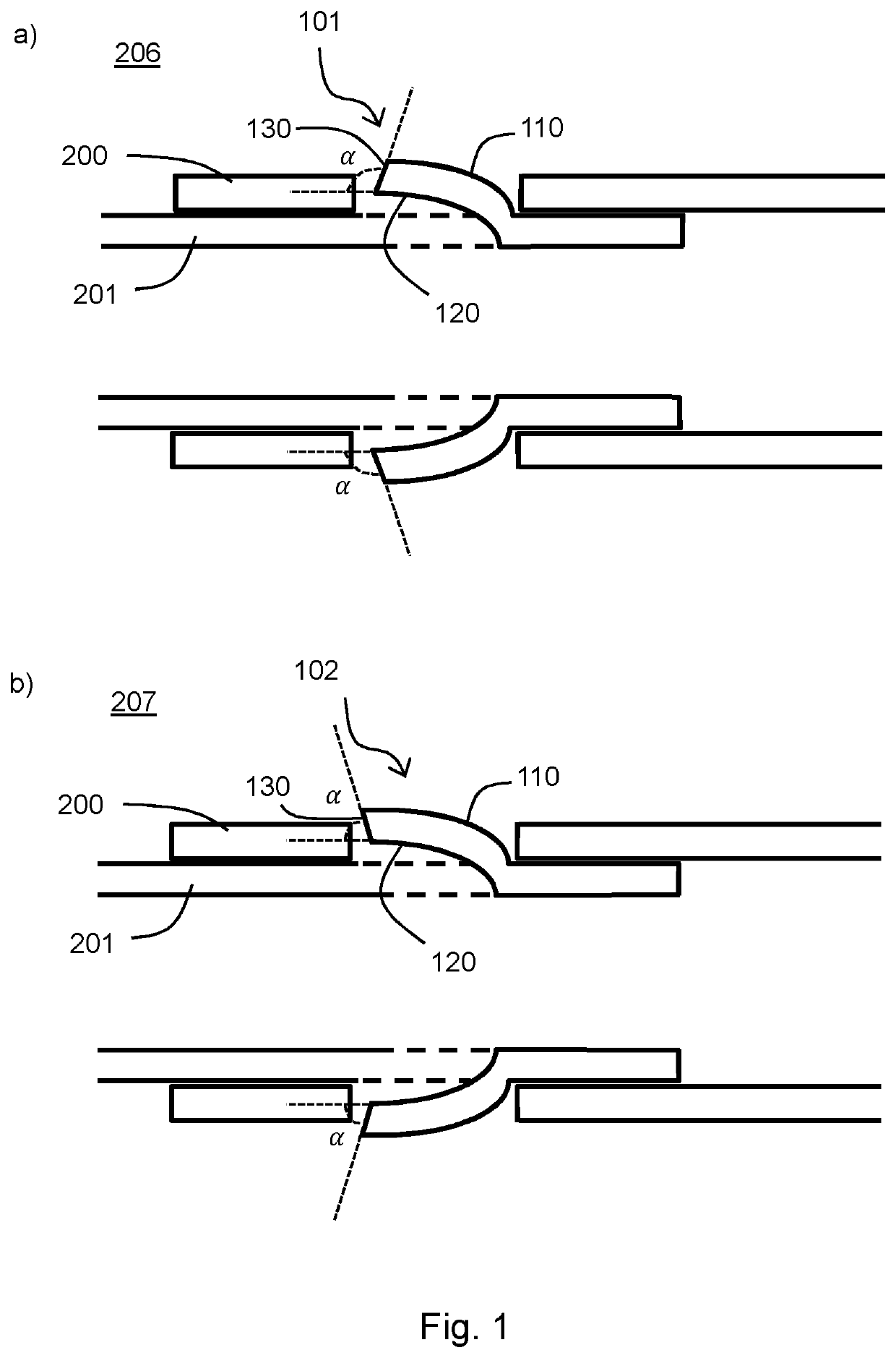
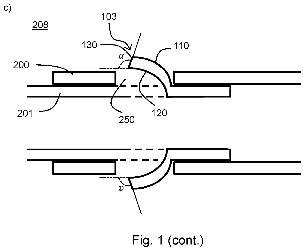
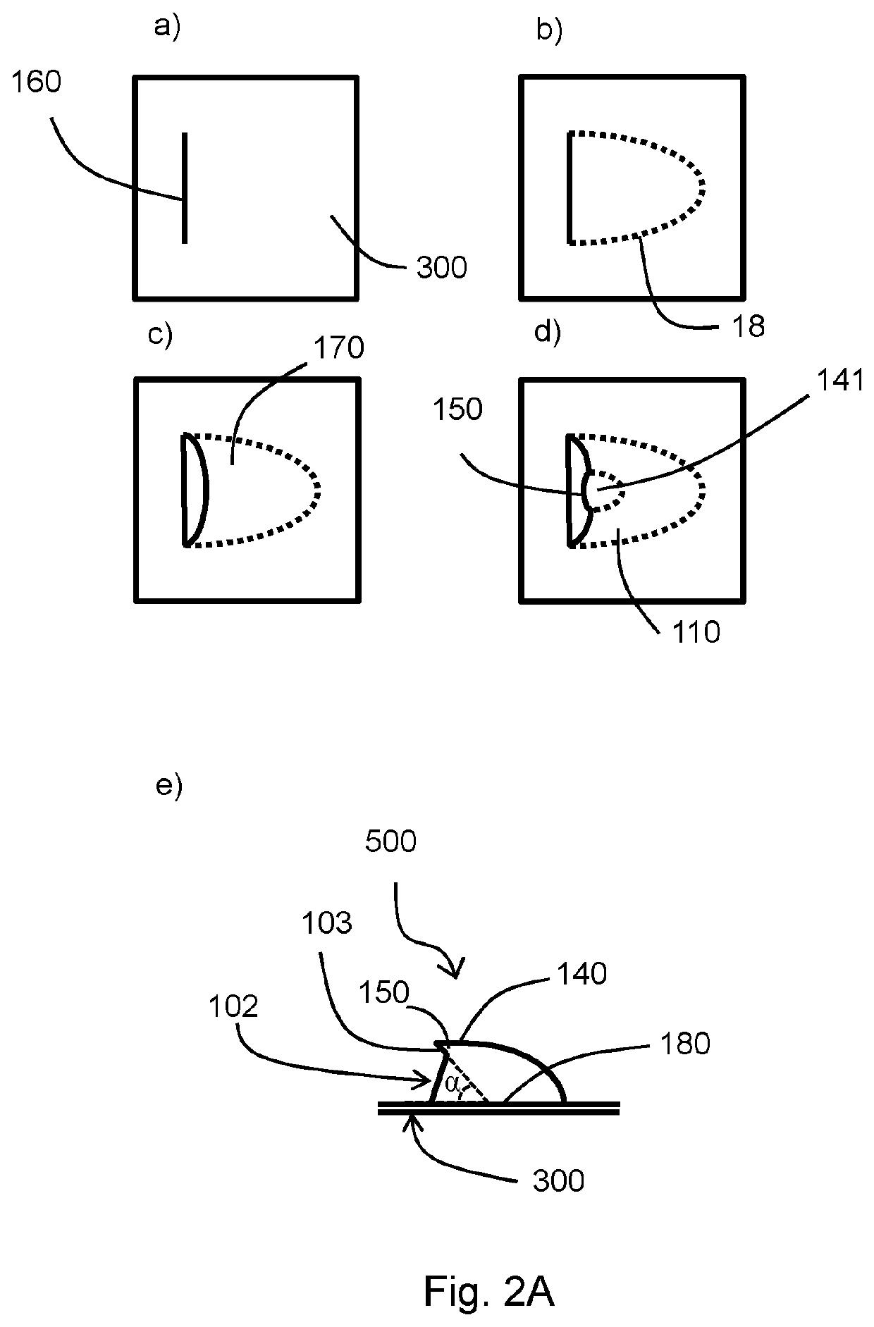
[0177]An assembly comprising two or more cable trays, with at least one of the two or several cable trays typically, but not necessarily, being elongate, each cable tray comprising:[0178]a bottom and two upright sides, the bottom and two upright sides preferably being made in one piece; and[0179]a first end extending as a continuation of the bottom and the upright sides and a second end extending as a continuation of the bottom and the upright sides, wherein each side of the first end comprises a barb and each side of the second end comprises a barb opening, wherein each first end and each second end are designed to mate in a sliding manner and to connect in a clickable manner.

specific embodiment 2

[0180]The assembly according to specific embodiment 1, wherein each first end is designed to overlap with a second end of a subsequent cable tray; each second end is designed to slidably receive a first end of a subsequent cable tray; each barb is designed to be clicked into a barb opening of a subsequent cable tray; and each barb opening is designed to slidably receive a barb of a subsequent cable tray.

specific embodiment 3

[0181]The assembly according to specific embodiment 1 or 2, wherein each of the upright sides comprises an inwardly folded upper longitudinal edge, wherein the inwardly folded upper longitudinal edge of the second end is provided to slidably receive the inwardly folded upper longitudinal edge of the first end of a subsequent cable tray.


PUM


Abstract

The present invention provides cable trays which can be pushed inside one another and can be clicked onto one another. Furthermore, assemblies are provided which comprise cable trays, barbs for cable trays and related methods.

Description

TECHNICAL FIELD[0001]The invention relates to cable trays, cable tray components, assemblies comprising cable trays, and related methods.TECHNOLOGICAL BACKGROUND OF THE INVENTION[0002]Housings for cables in buildings comprise cable trays which are connected to each other. Existing systems provide the connection of adjacent cable trays by means of additional components, such as plates, screws and plug-in systems. Thus, a connection is provided which offers sufficient stability and load bearing capacity.[0003]However, the use of additional components is laborious and not time-efficient: from a logistical point of view, the use of additional components is a drawback, and fitting and removal may also be difficult.[0004]Some existing connecting systems comprise the use of springs, but these systems are not compatible with certain current surface treatments, such as hot-dip galvanizing, which compromises their usefulness. In addition, these connecting systems are more difficult, and conse...

Claims


Application Information

Patent Timeline
Patent Type & Authority Applications(United States)
IPC IPC(8): H02G3/04F16L3/26F16B7/04
CPCF16B7/0406F16L3/26H02G3/0456H02G3/0608H02G3/04
Inventor AELVOET, LUCVAN EEGHEM, JEANVANDENBORRE, BERTENNIEUWENHUYSEN, TONY
Owner VERGOKAN
Why Eureka
Try Eureka