Processing method and processing device of conditioning electron gun

a processing device and electron gun technology, applied in the manufacture of electrode systems, electric discharge tubes/lamps, tube/lamp factory adjustment, etc., can solve the problems of reducing the operation rate of the drawing device, reducing the production yield, and causing a large amount of discharge at a high frequency, so as to achieve the effect of simply and easily enhancing the withstand voltage property of the electron gun

Active Publication Date: 2008-06-26
NUFLARE TECH INC
View PDF2 Cites 7 Cited by
  • Summary
  • Abstract
  • Description
  • Claims
  • Application Information

AI Technical Summary

Benefits of technology

[0020]According to the present invention, discharge factors existing on a surface of an electrode or an insulator forming an electr...

Problems solved by technology

Further, the electron bean originally required in an electron beam drawing process disappears to cause the production yield to be lowered by deterioration of the drawing accuracy, and to cause the operation rate of the drawing device to be lowered by stopping the operation of the drawing device.
However, in the past conditioning process of the electron gun, there are some cases in which massive discharge occurs at a high frequency in the conditioning process, the discharge causing damages such as roughening or cracks on the surfaces of the electrodes or the insulators of the electron gun.
Therefore, the life of the electron gun is p...

Method used


Image

  • Processing method and processing device of conditioning electron gun
  • Processing method and processing device of conditioning electron gun
  • Processing method and processing device of conditioning electron gun

Examples


first embodiment

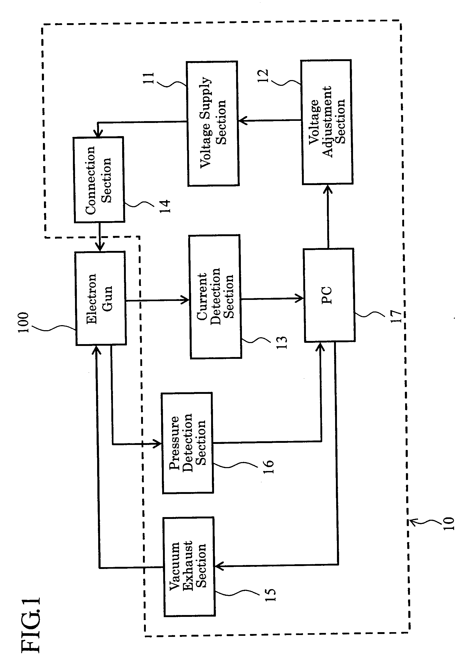
[0029]FIG. 1 is a schematic configuration diagram showing an example of a conditioning processing device of an electron gun according to a first embodiment. Here, although it is sufficient that the electron gun is an electron source for emitting an electron by a high electric field, the following embodiment is explained using an example of the electron gun attached to an electron beam drawing device as shown in FIG. 6.

[0030]As shown in FIG. 1, the conditioning processing device 10 of the electron gun of the present embodiment is provided with a voltage supply section 11 for supplying the electron gun 100 with a high voltage, a voltage adjustment section 12 for adjusting the voltage value of the voltage supply section 11, and a current detection section 13 for detecting the leakage current flowing between the electrodes of the electron gun 100. Here, it is arranged that the voltage supply section 11 applies a negative high voltage to the first electrodes 102 and the extraction electr...

second embodiment

[0056]The second embodiment has a feature of performing the conditioning process with a predetermined gas, with which the discharge is caused with relative ease, introduced inside the electron gun. FIG. 4 is a schematic configuration diagram showing an example of a conditioning processing device of an electron gun according to a second embodiment.

[0057]As shown in FIG. 4, the conditioning processing device 20 of the electron gun according to the second embodiment is provided with the voltage supply section 11 and the voltage adjustment section 12 for adjusting and supplying the high voltage to the electron gun 100, and the current detection section 13 for detecting the leakage current flowing between the electrodes of the electron gun 100 similarly to those explained in the first embodiment. Further, it is arranged that a negative high voltage is applied to the first electrodes 102 and the extraction electrode 107 connected via the connection section 14.

[0058]Further, a gas supply s...


PUM


Abstract

Discharge factors existing on a surface of an electrode or an insulator forming an electron gun are removed efficiently and effectively, thus simply and easily enhancing the withstand voltage property of the electron gun. A conditioning processing device of an electron gun is provided with a voltage supply section, a voltage adjusting section for adjusting the output voltage of the voltage supply section, and a current detection section for detecting a leakage current flowing between the electrodes of the electron gun. Further, there are attached a vacuum exhaust section for adjusting the inside of the electron gun in a reduced pressure condition and a pressure detection section. Further, it is arranged that a personal computer (PC), for example, performs data processing based on the leakage current detected by the current detection section or comparison with a reference value thereof to control the voltage, which is applied between the electrodes from the voltage supply section via a connection section, via the voltage adjustment section.

Description

CROSS REFERENCE TO RELATED APPLICATION[0001]This application is based upon and claims the benefit of priority from the prior Japanese Patent applications No. JP2006-259373, filed on Sep. 25, 2006; the entire contents of which are incorporated herein by reference.BACKGROUND OF THE INVENTION[0002]The present invention relates to a processing method and a processing device of conditioning an electron gun to improve the withstand voltage property thereof by removing a factor of discharge existing on a surface of an electrode or an insulator forming the electron gun.[0003]As shown in a schematic cross-sectional view of FIG. 6, an electron gun 100 used, for example, for an electron beam drawing device is disposed above an electron optical body tube 101, and is provided with a pair of first electrodes 102 (102a, 102b), a second electrode 102, and a third electrode 104 (e.g., a Wehnelt electrode).[0004]Here, in the operation of the electron beam drawing device, the inside of the electron be...

Claims


Application Information

Patent Timeline
IPC IPC(8): H01J9/50
CPCB82Y10/00B82Y40/00H01J9/445H01J2237/30411H01J37/3174H01J2237/022H01J37/063
Inventor MIYAMOTO, NOBUO
Owner NUFLARE TECH INC
Why Eureka
Try Eureka