Hermetic compressor

US20080145247A1Inactive Publication Date: 2008-06-19SAMSUNG GWANGJU ELECTRONICS CO LTD

Image

  • Hermetic compressor
  • Hermetic compressor
  • Hermetic compressor

Examples


Embodiment Construction

[0035]Reference will now be made in detail to an exemplary embodiment of a hermetic compressor, examples of which are illustrated in the accompanying drawings, wherein like reference numerals refer to like elements throughout. The embodiment is described below by referring to the figures.

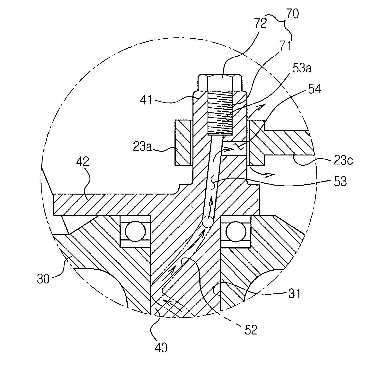
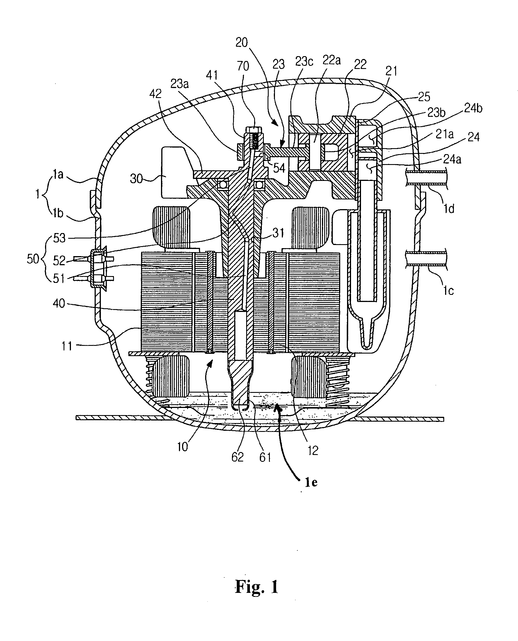
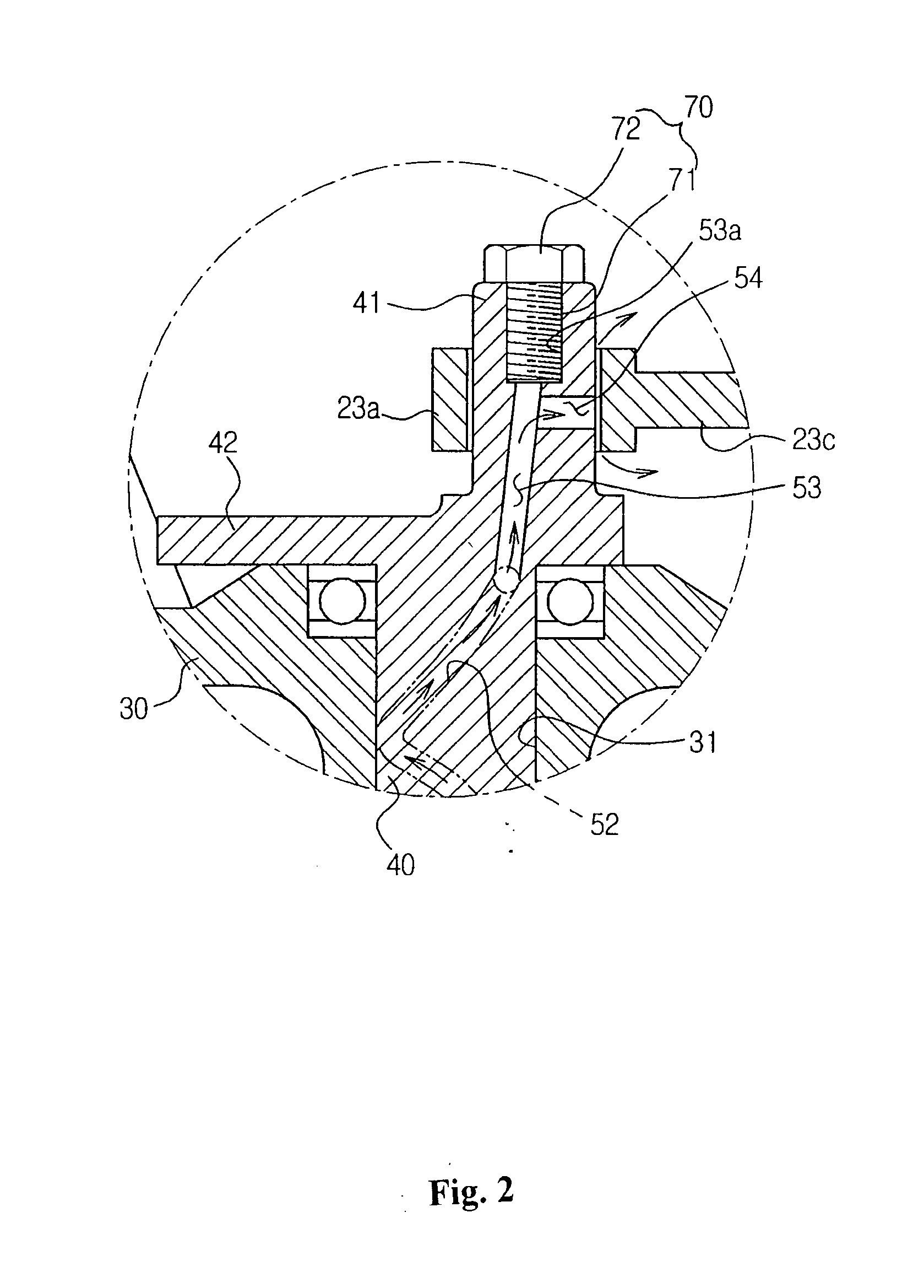
[0036]As shown in FIG. 1, the hermetic compressor includes a hermetic container 1 formed by coupling an upper container 1a and a lower container 1b to each other, the hermetic container 1 defining the outer appearance of the compressor. The hermetic container 1 is provided, at opposite sides thereof, with a suction pipe 1c to guide a refrigerant, passed through an evaporator of a refrigeration cycle, into the hermetic container 1 and with a discharge pipe 1d to guide the refrigerant, compressed within the hermetic container 1, to a condenser of the refrigeration cycle.

[0037]Provided within the hermetic container 1 are a drive unit 10 to provide power required to compress a refrigerant and a compress...


PUM


Abstract

A hermetic compressor including a drive unit, a piston, a rotating shaft including an eccentric shaft portion and a weight balance portion located below the eccentric shaft portion, and an oil flow path having an upper oil hole formed in the rotating shaft and adapted to allow oil to be suctioned upward and dispersed to the upper side of the eccentric shaft portion and an auxiliary oil hole to allow a part of the oil being suctioned upward along the upper oil hole to be supplied into a gap between the eccentric shaft portion and the connecting rod. The eccentric shaft portion is installed with a plug member to close an upper end of the upper oil hole. The plug member is configured to selectively couple a weight balance member, which is separately fabricated from the rotating shaft, to an upper end of the eccentric shaft portion.

Description

CROSS-REFERENCE TO RELATED APPLICATION[0001]This application claims the benefit of Korean Patent Application No. 2006-0129124, filed on Dec. 18, 2006 in the Korean Intellectual Property Office, the disclosure of which is incorporated herein by reference.BACKGROUND OF THE INVENTION[0002]1. Field of the Invention[0003]The present disclosure relates to a hermetic compressor, and, more particularly, to a hermetic compressor which can achieve oil lubrication between an eccentric shaft portion of a rotating shaft and a connecting rod, and employ a weight balance member that is separately fabricated from the rotating shaft so as to be coupled to the rotating shaft as occasion demands, in addition to a weight balance portion integrally formed at the rotating shaft for compensating for rotation unbalance caused by the eccentric shaft portion.[0004]2. Description of the Related Art[0005]In general, a hermetic compressor is employed in a refrigeration cycle of a refrigerator or air conditioner...

Claims


Application Information

Patent Timeline
19 Jun 2008
Publication
US20080145247A1
IPC
F04B39/02
CPC
F04B39/0022; F04B39/0253; F04B39/0094; F04B39/02; F04B39/00
Inventors
PARK, JONG IN