Method and system for lubricating a turbine engine

a technology for lubricating systems and turbine engines, which is applied in the direction of turbine/propulsion lubrication, climate sustainability, sustainable transportation, etc., can solve the problems of increasing the weight of the turbomachine, the risk of oil leaking from the enclosure, and the power generated by the rolling elements of the bearing is too small to justify such a lubrication system, etc., to achieve effective lubrication and mitigate the effect of drawbacks

Active Publication Date: 2011-08-18
SN DETUDE & DE CONSTR DE MOTEURS DAVIATION S N E C M A
View PDF5 Cites 17 Cited by
  • Summary
  • Abstract
  • Description
  • Claims
  • Application Information

AI Technical Summary

Benefits of technology

A main object of the present invention is thus to mitigate such drawbacks by proposing a method and a system for lubricating a turbomachine having at least three distinct enclosures, each containing at least one rolling bearing, and enabling the rolling bearings to be lubricated effectively without having recourse to complicated arrangements.
The term “oil mist” is used to mean a stream of air carrying droplets of oil in suspension. When the rolling bearing of the secondary enclosure has a speed of rotation that is low relative to that of the bearings in the main enclosures (e.g. of the order of 1000 rpm), the use of an oil mist coming from at least one of the main enclosures suffices amply for ensuring good lubrication of the bearings. This results in the lubrication system being simplified and lightened (by omitting an oil nozzle, a recovery pump, a degassing channel, and de-oilers).

Problems solved by technology

Such a lubrication method presents various drawbacks.
Discharging the oil and the air carrying oil droplets also requires the use of recovery pumps and a de-oiler, thereby increasing the weight of the turbomachine.
These drawbacks are acceptable once the thermal power generated by the rolling bearings of the turbomachine is high enough to justify having recourse to such a lubrication system.
In contrast, when the rolling elements of one of the bearings of the turbomachine rotate at a speed that is relatively low (e.g. of the order of 1000 rpm), the power generated by the rolling elements of the bearing is too small to justify having recourse to such a lubrication system.
In such a situation, it can happen that an excessive flow of lubricating oil is injected into the enclosure containing the rolling bearing that operates at a low speed of rotation, and there is a risk of oil leaking from the enclosure.

Method used


Image

  • Method and system for lubricating a turbine engine
  • Method and system for lubricating a turbine engine
  • Method and system for lubricating a turbine engine

Examples


Embodiment Construction

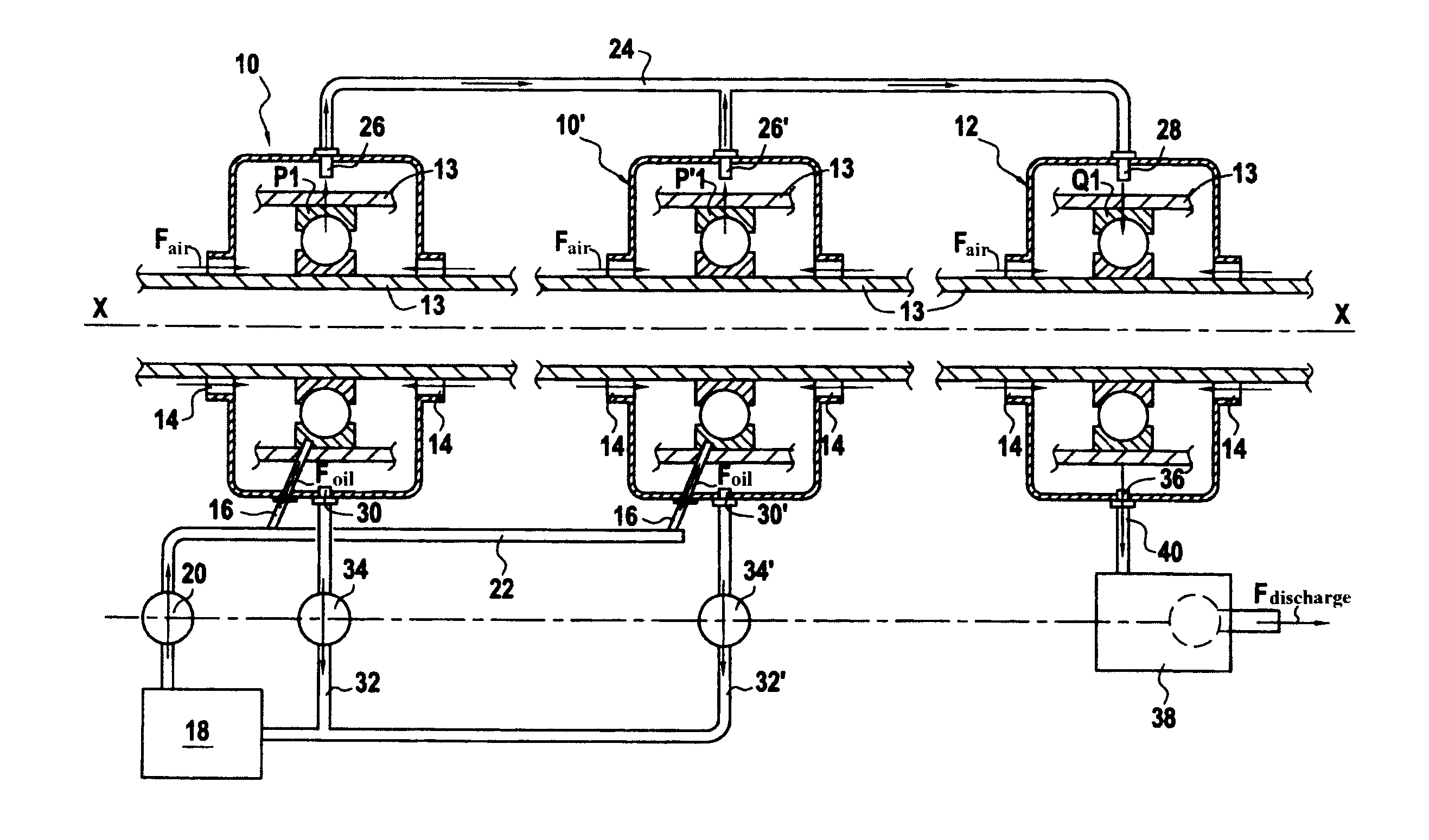
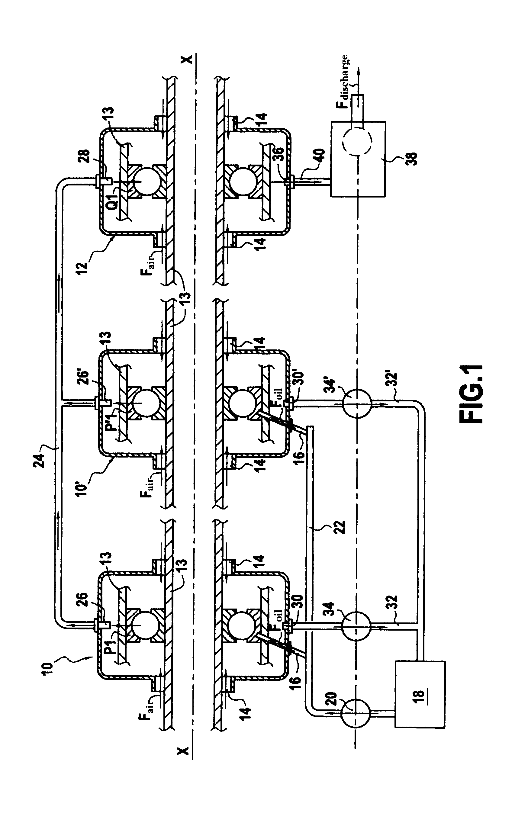
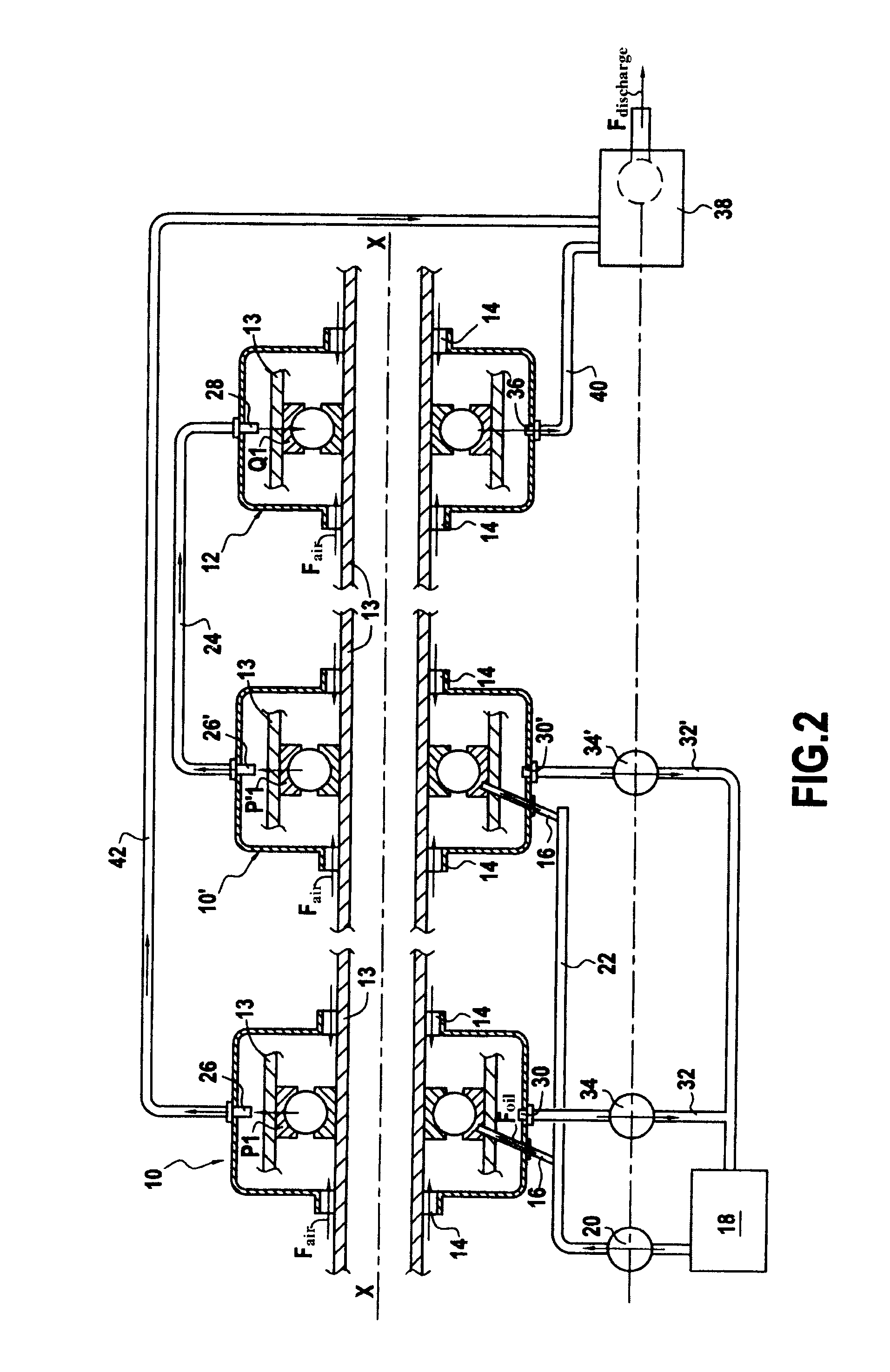
The invention applies to any aviation turbomachine having at least three enclosures containing rolling bearings. It applies more particularly to a turbomachine having a two-stage contrarotating fan.

FIG. 1 is a highly diagrammatic view of a lubrication system applied to a turbomachine having a two-stage contrarotating fan.

The turbomachine has a longitudinal axis X-X with three distinct annular enclosures, namely: two so-called “main” enclosures 10 and 10′ formed at the upstream end of the turbomachine and each containing at least one rolling bearing, respectively P1 and P′1, and a so-called “secondary” enclosure 12 formed downstream and containing at least one rolling bearing Q1. For convenience, only one bearing is shown per enclosure in FIG. 1. Naturally, each enclosure could have more than one bearing.

In well-known manner, these various rolling bearings (which may be ball bearings or roller bearings) support various spools of the turbomachine in rotation in order to take up radial...


PUM


Abstract

A method and a system for lubricating a turbine engine including at least three separate housings each including at least one roller bearing. The method pressurizes the housings through seals, of which two main housings are pressurized at a pressure higher than that of a remaining secondary housing, lubricates a secondary roller bearing only by injecting an oil mist from at least one of the main housings, the oil mist being supplied by a pressure difference between the main housings and the secondary housing, recovers a remainder of the lubrication oil injected into the main housings to supply the same to an oil tank, and supplies the air / oil mixture from the secondary housing to an oil separator.

Description

BACKGROUND OF THE INVENTIONThe present invention relates to the general field of dynamic lubrication of an aviation turbomachine.An aviation turbomachine has numerous elements that need to be lubricated; these include in particular rolling bearings used for supporting its shafts in rotation, and also the gears of its accessory drive gearbox.In particular, in order to reduce friction, wear, and heating due to the high speed of rotation of the shafts of the turbomachine, the rolling bearings that support them need to be lubricated. Since simple lubrication by injecting oil solely during periods of turbomachine maintenance do not suffice, recourse is generally had to so-called “dynamic” lubrication.Dynamic lubrication consists in putting oil into continuous circulation in a lubrication circuit. A flow of lubricating oil coming from a tank is thus delivered by a pump against the rolling elements of the bearings, which bearings are housed in enclosures that are closed by sealing gaskets....

Claims


Application Information

Patent Timeline
Patent Type & Authority Applications(United States)
IPC IPC(8): F01D25/18F01M11/08F01D25/20F02C7/06
CPCF01D25/125F01D25/16F01D25/183Y02T50/675F02C7/06F05D2240/40F01D25/20Y02T50/60
Inventor CHARIER, GILLES ALAINGAUTHIER, GERARD PHILIPPEGILLE, LAURENTMORREALE, SERGE RENE
Owner SN DETUDE & DE CONSTR DE MOTEURS DAVIATION S N E C M A
Why Eureka
Try Eureka