Lubrication system for a differential of a driven axle and automotive vehicle comprising such a lubrication system

a technology of lubrication system and driven axle, which is applied in the direction of mechanical equipment, gearing details, gearing, etc., can solve the problems of high lubricant amount, complex electronic control of the transfer of lubricant from the tank to the sump, and inability to provide satisfying lubrication. , to achieve the effect of improving lubricant level management and efficient lubrication

Active Publication Date: 2015-06-09
VOLVO LASTVAGNAR AB
View PDF13 Cites 18 Cited by
  • Summary
  • Abstract
  • Description
  • Claims
  • Application Information

AI Technical Summary

Benefits of technology

[0008]Thanks to an aspect of the invention, the auxiliary lubricant tank is filled by the rotation of the crown wheel and allows an efficient lubrication, by gravity, of critical parts of the differential, such as the pinion bearings and / or the interior of the differential, by directly bringing the lubricant to these areas. This permits to improve the lubricant level management.

Problems solved by technology

In case a low lubrication level is needed, for example, when low torques are to be transmitted, too high an amount of lubricant induces excessive power losses due to the resistance of the lubricant to the rotation of the crown wheel, which partially takes place in the lubricant.
Such a lubrication system does not provide a satisfying lubrication at the interface between the crown wheel and the pinion, in the bearings of the pinion and in the interior of the differential, because these areas are not easy to access.
Therefore, this can lead to scoring on the elements of the differential, and to critical heating of the pinion bearings, which are located in a place which is generally above the lubricant level in the sump.
Moreover, the electronic control of the transfer of lubricant from the tank to the sump is complex, expensive and not always perfectly reliable.

Method used


Image

  • Lubrication system for a differential of a driven axle and automotive vehicle comprising such a lubrication system
  • Lubrication system for a differential of a driven axle and automotive vehicle comprising such a lubrication system
  • Lubrication system for a differential of a driven axle and automotive vehicle comprising such a lubrication system

Examples


Embodiment Construction

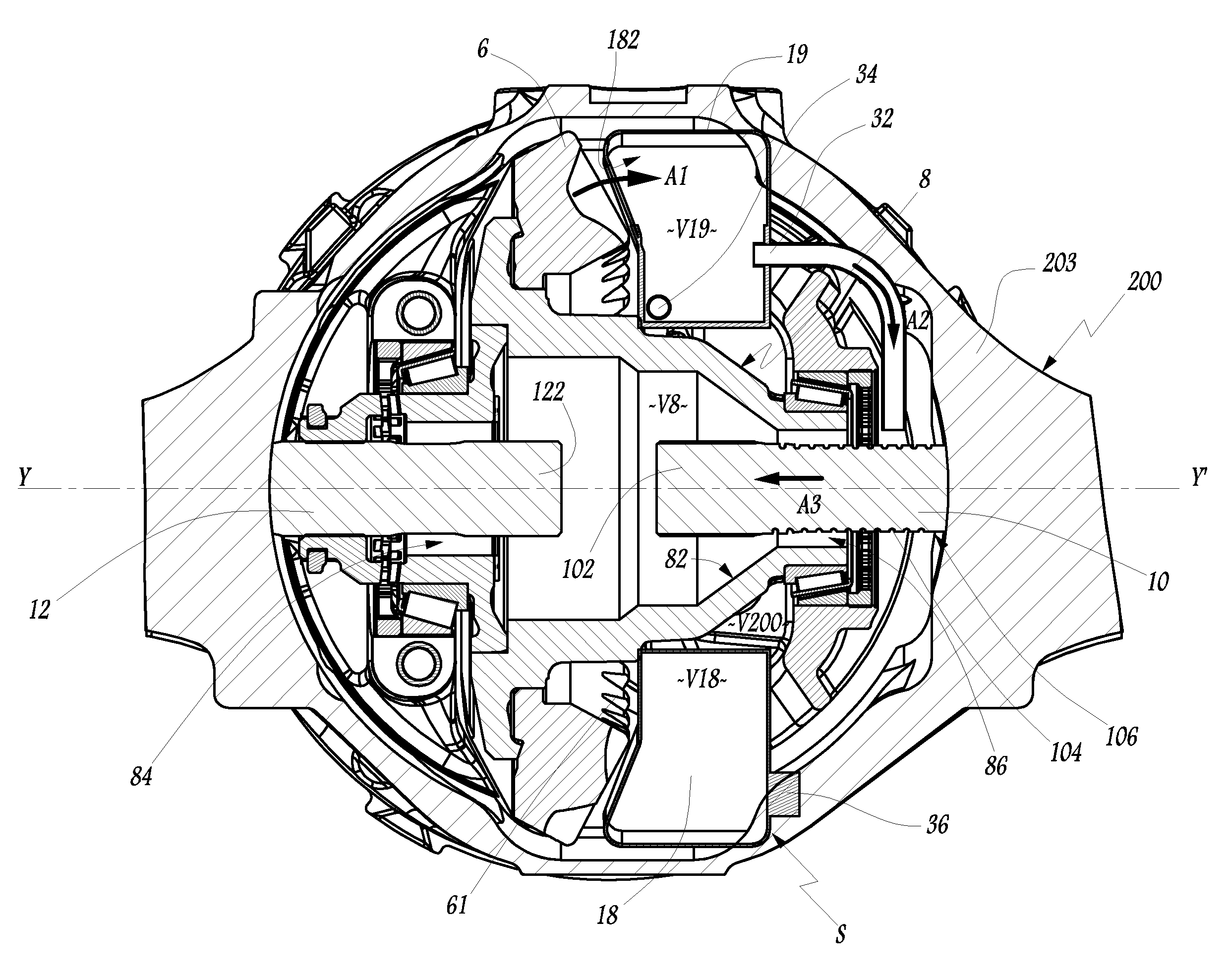
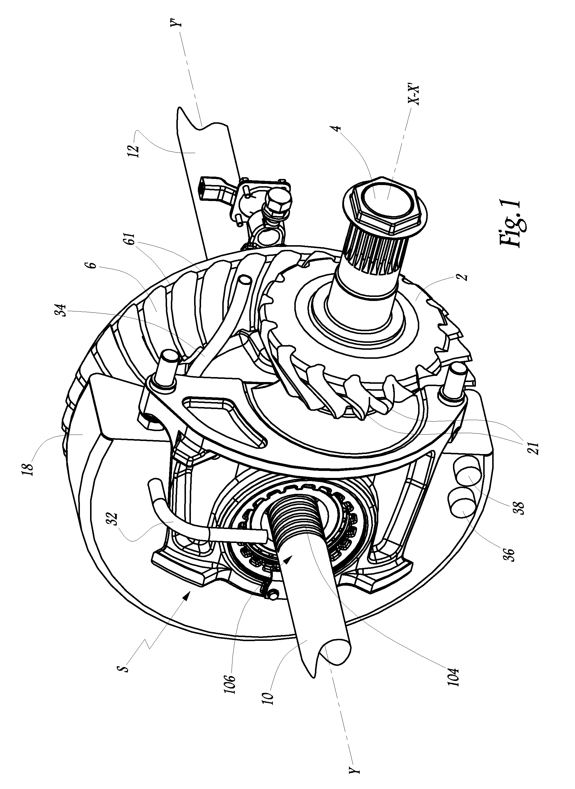
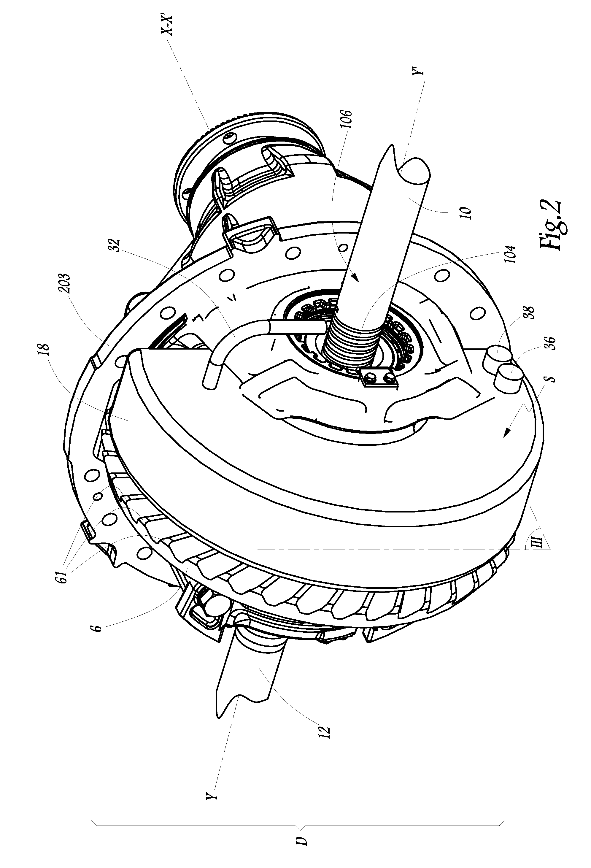
[0031]The lubrication system S represented on FIGS. 1 to 6 is to be integrated in a differential D of a driven axle of an automotive vehicle, such as a truck. This differential comprises a pinion 2 connected to a drive shaft 4, which is driven by a non-shown engine of the vehicle. Pinion 2 meshes with a crown wheel 6 which is fast in rotation with a satellite carrier 8. Carrier 8 and crown wheel 6 rotate together around an axis Y-Y′, while pinion 2 and drive shaft 4 rotate around an axis X-X′ which is perpendicular to axis Y-Y′.

[0032]Axis Y-Y′ corresponds to the rotation axis of the wheels of the vehicle which are not represented on the figures. Wheels are driven, by two wheel shafts 10 and 12 which comprise, at their ends 102 and 122 located on the side opposite to the wheels, nonrepresented gear wheels adapted to mesh with two or more non-shown satellite gears rotating with respect to carrier 8 in an interior volume V8 of carrier 8. Depending on the design of the differential, the...


PUM


Abstract

This lubrication system for a differential of a driven axle on an automotive vehicle includes a sump in which is located a crown wheel driven by a pinion, the crown wheel being fast in rotation with a carrier, and a main lubricant tank having an inlet port and at least one outlet port. Rotation of the crown wheel causes lubricant to be transferred from the sump to the main tank via the inlet port, and the outlet port allows the lubricant to pass from the main tank to the sump. The lubrication system includes an auxiliary lubricant tank located in the sump, adapted to be filled in with lubricant by rotation of the crown wheel, and an arrangement to convey lubricant from auxiliary tank to a lubricant needing portion of the differential.

Description

BACKGROUND AND SUMMARY[0001]The invention relates to a lubrication system for a differential of a driven axle. The invention also relates to an automotive vehicle equipped with such a lubrication system.[0002]Automotive vehicle such as cars or trucks are generally equipped with one or several differentials on their driven axles. Differentials need lubrication in order to prevent damages such as scoring on the various elements of the differential. Differentials are commonly lubricated by splash lubrication. The differential is for example contained in an axle housing having a central part in the shape of a bulb which forms a sump partly filled with lubricant. The crown wheel, which forms the outer part of the differential, has its lower part immersed in the lubricant of the sump so that, when it rotates, it splashes the lubricant all over in the central part axle housing, thereby lubricating various parts of the differential. In case of transmission of high torques in the differentia...

Claims


Application Information

Patent Timeline
Patent Type & Authority Patents(United States)
IPC IPC(8): F16H57/04F16H48/38
CPCF16H57/0483F16H57/0409F16H57/045F16H57/0471F16H57/0423F16H57/0428
Inventor BARILLOT, THOMAS
Owner VOLVO LASTVAGNAR AB
Why Eureka
Try Eureka