Minimal quantity lubrication (MQL) supply system for processing of outer-cooling type high-speed machine tool and inner-cooling type high-speed machine tool

A technology of minimal quantity lubrication and supply system, which is applied in the direction of metal processing equipment, metal processing machinery parts, manufacturing tools, etc., to achieve the effects of no waste liquid discharge, cost reduction, and good lubrication and cooling effects

Inactive Publication Date: 2012-07-04
DG ARMORINE ENERGY EFFICIENT & ECO FRIENDLY TECH
View PDF4 Cites 14 Cited by
  • Summary
  • Abstract
  • Description
  • Claims
  • Application Information

AI Technical Summary

Problems solved by technology

[0011] The technical problem to be solved by the present invention is: to overcome the technical existing problems of the above micro-lubrication devices, and to design a micro-quantity lubrication supply system that can generate fine dry oil mist, and this system can ensure that the oil mist can overcome the influence of centrifugal force and pass smoothly. The high-speed rotating spindle inner hole and tool inner hole reach the pr

Method used


Image

  • Minimal quantity lubrication (MQL) supply system for processing of outer-cooling type high-speed machine tool and inner-cooling type high-speed machine tool
  • Minimal quantity lubrication (MQL) supply system for processing of outer-cooling type high-speed machine tool and inner-cooling type high-speed machine tool
  • Minimal quantity lubrication (MQL) supply system for processing of outer-cooling type high-speed machine tool and inner-cooling type high-speed machine tool

Examples


Example Embodiment

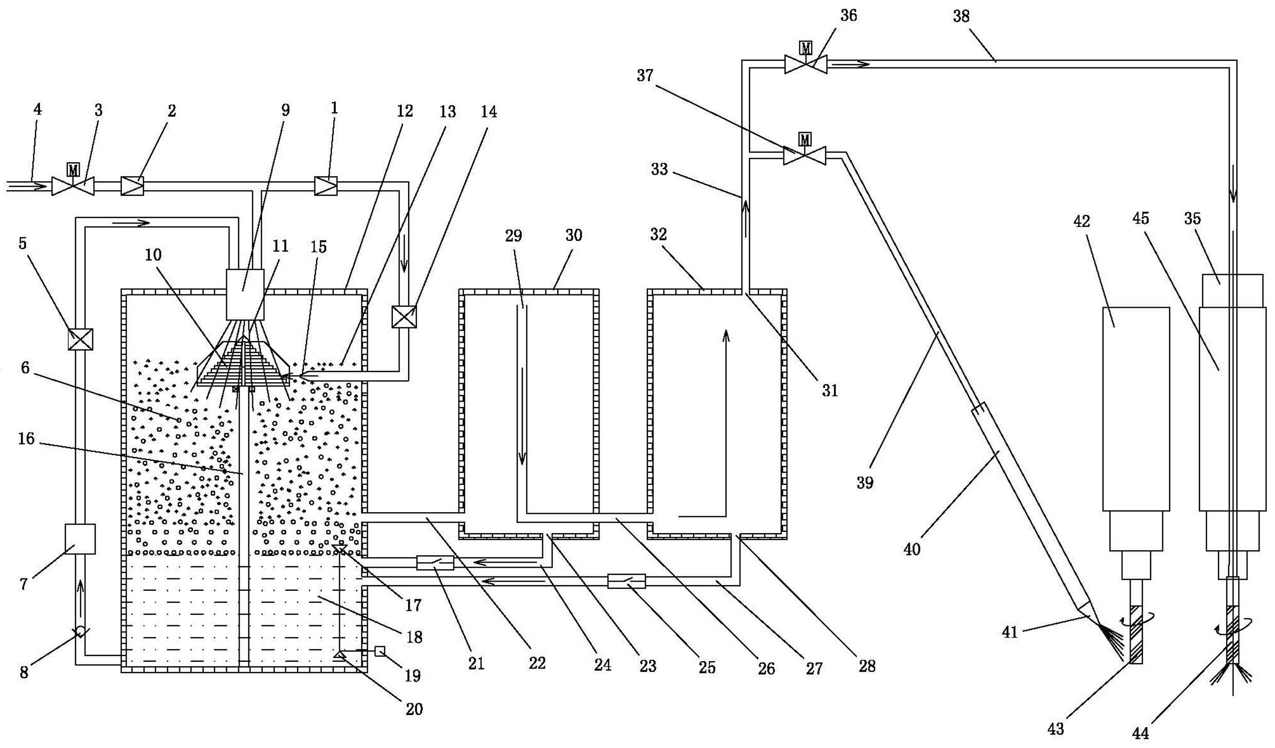
[0033] Example 1, such as figure 1 As shown, the micro-lubrication supply system for external cooling and internal cooling high-speed machine tool processing in this embodiment includes:

[0034] The atomization chamber 12 equipped with cutting oil 18 is provided with a fine atomization nozzle 9 at the center of the upper part of the inner cavity of the atomization chamber 12;

[0035] A solenoid valve 3 and filter pressure reducing valve 2, A solenoid valve 3, filter pressure reducing valve 2 and fine atomizing nozzle 9 are connected together in sequence via a gas delivery pipe 4;

[0036] The proportional pressure reducing valve 1, the A gas flow control valve 14 and the gas nozzle 15 arranged in the atomizing chamber 12, the filter pressure reducing valve 2, the proportional pressure reducing valve 1, the A gas flow control valve 14 and the gas nozzle 15 The gas delivery pipes 4 are connected together in sequence;

[0037] The oil volume control valve 5, the micro oil pump 7 and th...

Example Embodiment

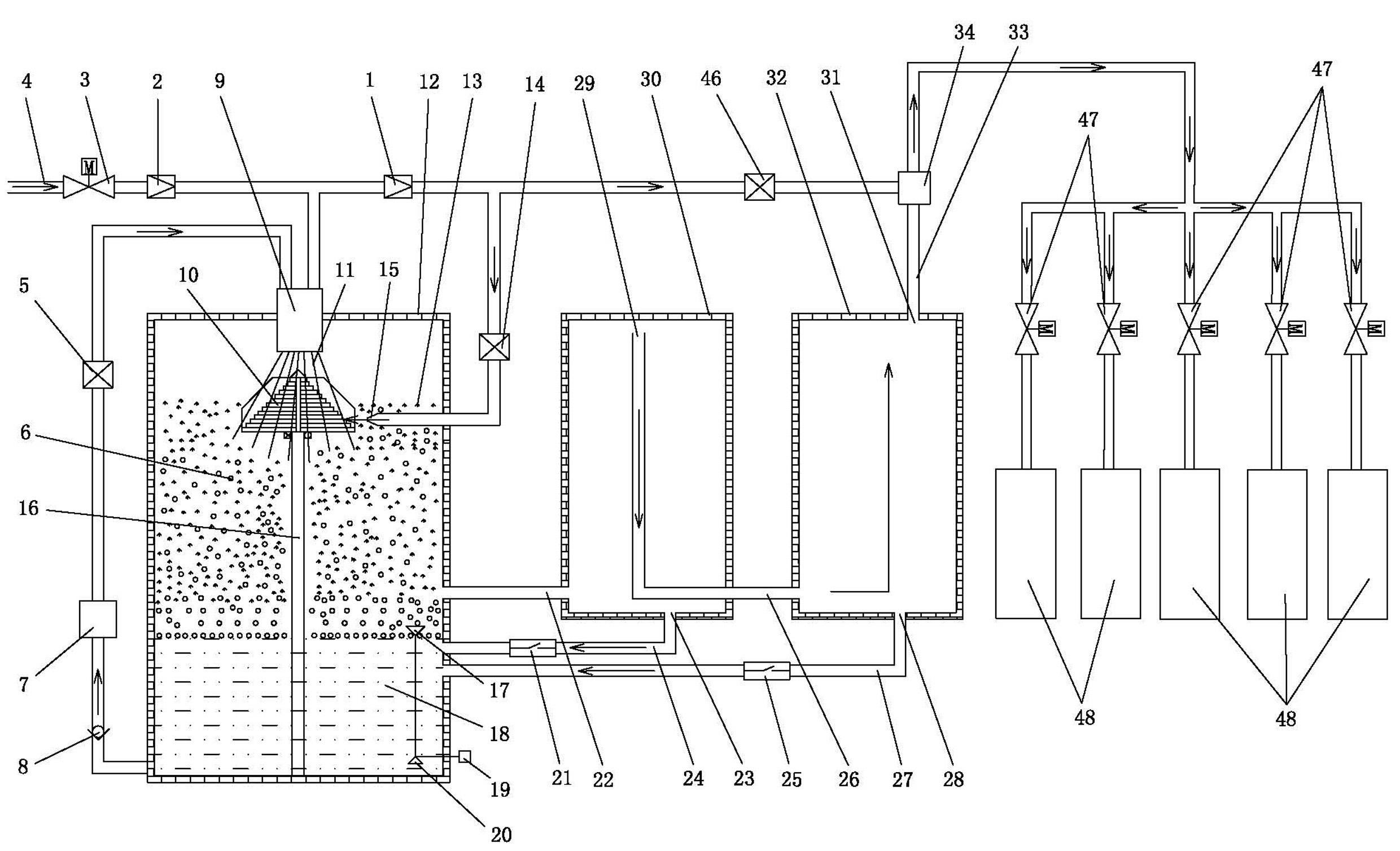
[0055] Example 2, such as figure 2 As shown, the micro-lubrication supply system for external cooling and internal cooling high-speed machine tool processing described in this embodiment has a larger gas flow rate and can be adjusted, and is suitable for oil and gas volume. The demand is large, especially in the workplace where the gas demand is large. For example, it is used for large-scale machining centers and large-scale internal cooling drilling machines with large tool sizes, multi-station machining centers for simultaneous processing of multiple tools, CNC composite turning and milling centers, combined machine tools, and processing machine groups composed of multiple machine tools. The structure in Embodiment 2 that is different from Embodiment 1 is: this embodiment also includes a B gas flow control valve 46 and a three-way 34. The proportional pressure reducing valve 1, the B gas flow control valve 46 and the three-way 34 are transported by gas. The pipes 4 are conne...


PUM

PropertyMeasurementUnit
Diameteraaaaaaaaaa

Abstract

The invention relates to a minimal quantity lubrication (MQL) supply system for processing of an outer-cooling type high-speed machine tool and an inner-cooling type high-speed machine tool, which mainly comprises a cutting oil atomizing chamber, a fine atomizing spray head, an electromagnetic valve A, a filtering pressure-reducing valve, a proportional pressure-reducing valve, a gas flow control valve A, a gas nozzle, an oil quantity control valve, a minitype oil pump, a one-way valve, a primary sedimentation chamber, a secondary sedimentation chamber and a cone-shaped body component, wherein the fine atomizing spray head is arranged at the upper part of an inner cavity of the atomizing chamber; the electromagnetic valve A, the filtering pressure-reducing valve and the fine atomizing spray head are sequentially connected together by gas delivery pipes; the filtering pressure-reducing valve, the proportional pressure-reducing valve, the gas flow control valve A and the gas nozzle are sequentially connected together by gas delivery pipes; the oil quantity control valve, the minitype oil pump and the one-way valve are sequentially connected together by oil pipes; the atomizing chamber is connected with the primary sedimentation chamber by an oil mist connecting pipe A; and the primary sedimentation chamber is connected with the secondary sedimentation chamber by an oil mist connecting pipe B. The MQL supply system is used for lubricating and cooling a processing area in mechanical processing.

Description

technical field [0001] The invention relates to a system capable of generating fine oil mist, which can ensure that the oil mist can overcome the influence of centrifugal force, and smoothly pass through the high-speed rotating spindle and the inner hole of the tool to reach the processing area, and can also be used for the lubrication and cooling of externally cooled tools. The invention belongs to the technical field of high-speed and high-efficiency green cutting in mechanical processing. Background technique [0002] At present, the environment, resources, and population have become the three major problems facing the world. The deterioration of the global environment is increasing day by day, which is posing a serious threat to the survival and development of human society. In the process of transforming manufacturing resources into products, the manufacturing industry produces a large amount of waste, which forms the main source of pollution to the environment by the m...

Claims


Application Information

Patent Timeline
IPC IPC(8): B23Q11/10
Inventor 熊伟强
Owner DG ARMORINE ENERGY EFFICIENT & ECO FRIENDLY TECH
Why Eureka
Try Eureka