Projected roller plane

A flat and end face technology, applied in the direction of roller table, roller column, furnace, etc., can solve the problems of metal pivot oxidation, hindering rotation, restricting cylinder rotation, etc.

Active Publication Date: 2009-10-28
FM LTD
View PDF0 Cites 1 Cited by
  • Summary
  • Abstract
  • Description
  • Claims
  • Application Information

AI Technical Summary

Problems solved by technology

[0013] In cases where the water contains corrosive chemicals, this infiltration can lead to oxidation of the metal pivot, which restricts the rotation of the cylinder on the pivot, even to the extent that it hinders it

Method used


Image

  • Projected roller plane
  • Projected roller plane
  • Projected roller plane

Examples


Embodiment Construction

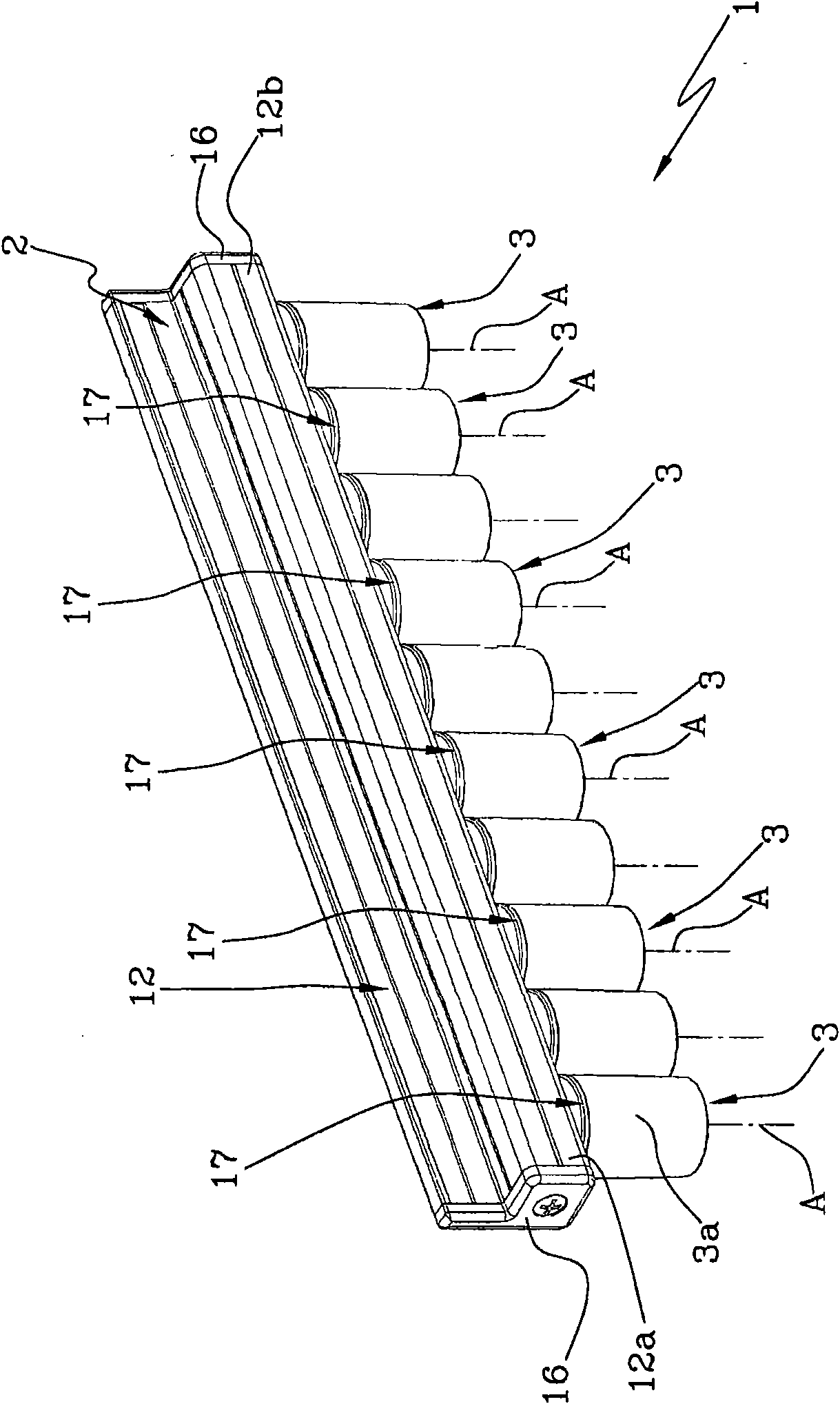
[0025] Referring to the accompanying drawings, number 1 represents the roller plane of the present invention as a whole.

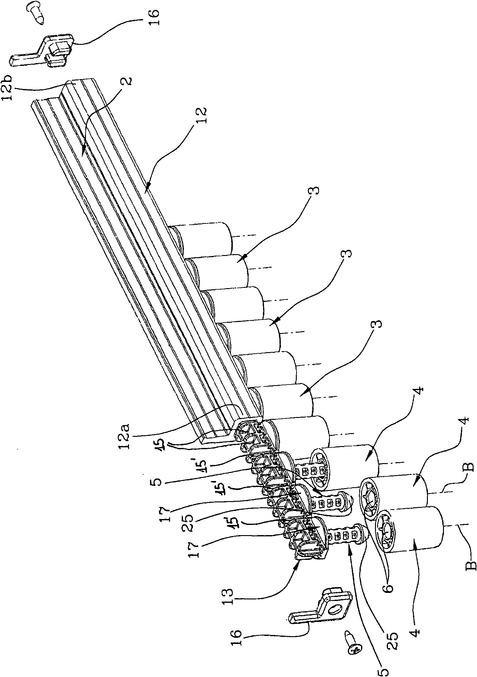
[0026] The roller plane 1 comprises a support 2 and a plurality of rollers 3 which are rotatably and protrudingly associated to the support 2 .

[0027] The support 2 , which will be described in more detail herein below, is fixed in a predetermined orientation along a transport line (not shown) such that the roller plane 1 defines the edges and / or slide tracks of said article transport line.

[0028] The rollers 3 are arranged with their axes of rotation A parallel to each other.

[0029] In the described embodiment, the roller plane 1 is prearranged to be mounted such that the axis of rotation A of the roller 3 is arranged on a preferably inclined plane, while the roller 3 is inclined downward in a direction spaced from the support 2 .

[0030] More preferably, the axis of rotation A of the roller 3 is on a substantially vertical plane.

[0031] In an ...


PUM


Abstract

A roller plane comprises a supporting member (2) and a plurality of rollers (3); the rollers (3) are associated onto the supporting member (2), and can rotate around the rotation axis (A); each roller(3) includes a rotary part (4) which rotates around the longitudinal axis (B); the supporting member (2) includes at least one pivot (5) which is inserted into the hole (6) of the rotary part (4), and associated onto the supporting member (2). The roller plane also comprises discs (17) each of which is perpendicular to the vertical to (A), and is arranged between each pivot (5) and the supportingmember (2).

Description

technical field [0001] The invention relates to a roll plane. In particular, the invention relates to a protruding roller flat. [0002] The invention is advantageously applied in industrial transportation lines. [0003] In particular, the invention is effectively applied to realize lateral edges in transport lines of articles having a particularly small thickness, for example like glass panels, tiles or the like. [0004] In addition, the present invention is effectively used to realize a sliding bearing surface of an article. Background technique [0005] The protruding roll plane includes a support for securing the roll plane in a desired position along the conveying line of the flat products. [0006] The support comprises a suitably shaped profile and a base insertable into a seat provided in the profile. [0007] Mounted on the base are metal pivots which are parallel to each other and support respective cylinders for respective rollers defining a roller plane. ...

Claims


Application Information

Patent Timeline
Patent Type & Authority Applications(China)
IPC IPC(8): B65G13/00B65G39/02B65G49/06
CPCB65G13/00B65G39/09
Inventor B·弗兰基尼
Owner FM LTD
Why Eureka
Try Eureka