Flue gas distributor

A distributor and flue gas technology, applied in separation methods, dispersed particle separation, chemical instruments and methods, etc., can solve problems such as complex structure, dead bed formation, poor redistribution effect, etc.

Inactive Publication Date: 2009-11-25
ZHENJIANG CITY POWER STATION AUXILIARY MACHINERY PLANT +1
View PDF0 Cites 2 Cited by
  • Summary
  • Abstract
  • Description
  • Claims
  • Application Information

AI Technical Summary

Problems solved by technology

At present, the most widely used distribution devices in large-scale flue gas desulfurization in China are louver-type flue gas distributors and flue gas distribution plates. The former has a poor effect on the redistribution of desulfurizers and gases in the desulfurization tower, which affects the utilization of desulfurizers. rate, the flue gas desulfurization efficiency is low; the latter has a better distribution effect on flue gas and desulfurizing agent, but the structure is complex and the resistance is relatively large, and the solid desulfurizing agent is easy to form a dead bed on the surface of the distribution plate. It is easy to block the holes of the distribution plate under certain conditions, and it is difficult to maintain

Method used


Image

  • Flue gas distributor
  • Flue gas distributor
  • Flue gas distributor

Examples


Embodiment Construction

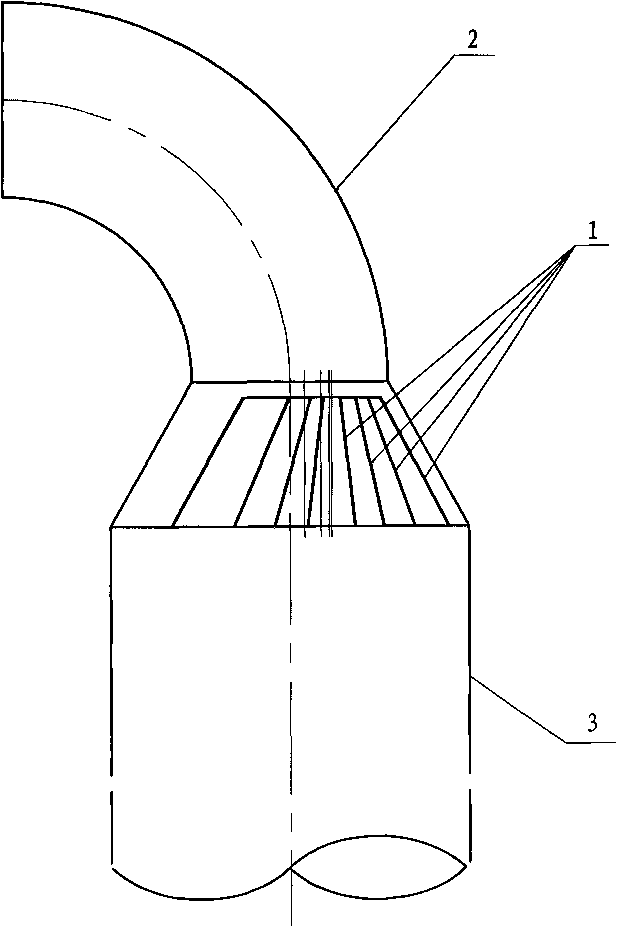
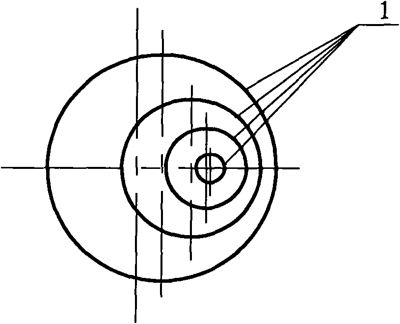
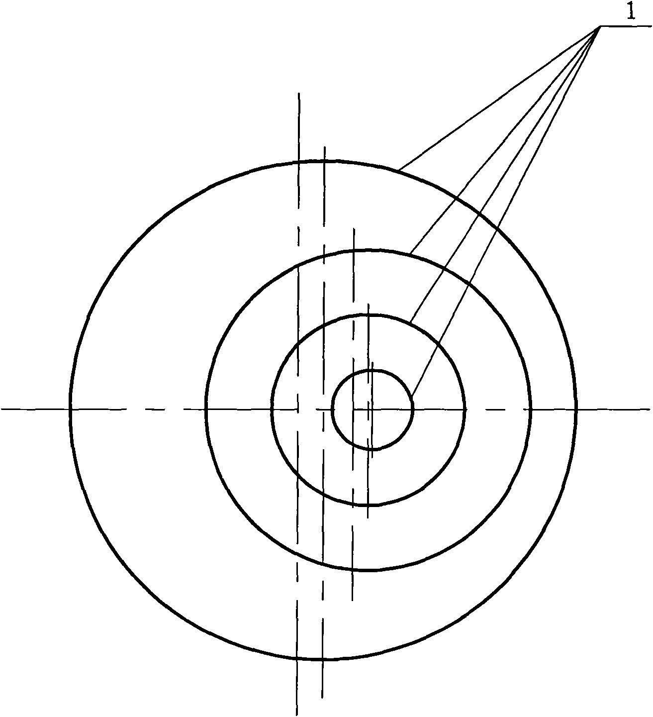
[0009] As shown in the figure, the smoke distributor includes a plurality of conical cylinders 1 with different maximum diameters. The upper end of the conical cylinders with a smaller diameter communicates with the smoke inlet pipe through a section of elbow 2. The conical cylinders The lower end with a larger diameter is connected to the desulfurization tower 3, and each conical cylinder is sequentially set according to the size of the maximum diameter, wherein the center line of the conical cylinder with a smaller maximum diameter is opposite to the conical cylinder with a larger maximum diameter on its periphery. The center line of the cylinder is offset to one side by a certain distance, and the direction of offset is the side close to the larger bending radius of the elbow 2, that is, on the side closer to the larger bending radius of the elbow 2, each The walls of the conical cylinders 1 are relatively dense, while the walls of the conical cylinders 1 are relatively spar...


PUM


Abstract

The invention relates to a flue gas distributor in a flue gas desulfurizing device. The flue gas distributor comprises a plurality of conical barrels with unequal maximum diameters. The smaller upper end of the conical barrel is communicated with a flue gas inlet pipe through a section of bend pipe. The larger lower end of the conical barrel is communicated with a desulfurizing tower. The conical barrels are sleeved according to the dimension of the maximum diameter. The center line of the conical barrel with the smaller maximum diameter shifts a distance relative to the center line of the conical barrel with the larger maximum diameter. The shift direction is closed to one side of the bend pipe with a larger bend radius. The invention can make the gas and the desulfurizer distribute uniformly in the desulfurizing tower and has the simple structure, easy maintenance, low wearing degree, no flow dead area and small pressure loss.

Description

technical field [0001] The invention relates to a flue gas distributor used in a flue gas desulfurization device. Background technique [0002] The flue gas distributor in the flue gas desulfurization device is usually installed at the flue gas inlet of the desulfurization tower, and it is usually connected by an elbow pipe into the flue gas pipe. At present, the most widely used distribution devices in large-scale flue gas desulfurization in China are louver-type flue gas distributors and flue gas distribution plates. The former has a poor effect on the redistribution of desulfurizers and gases in the desulfurization tower, which affects the utilization of desulfurizers. rate, the flue gas desulfurization efficiency is low; the latter has a better distribution effect on flue gas and desulfurizing agent, but the structure is complex and the resistance is relatively large, and the solid desulfurizing agent is easy to form a dead bed on the surface of the distribution plate. ...

Claims


Application Information

Patent Timeline
Patent Type & Authority Applications(China)
IPC IPC(8): B01D53/74B01D53/50F23J15/00
Inventor 王凡张凡刘宇田刚王红梅石应杰林军虞瑞鹤
Owner ZHENJIANG CITY POWER STATION AUXILIARY MACHINERY PLANT
Why Eureka
Try Eureka