A feed distributor for a fixed bed reactor operating in full liquid phase

A technology of distributor and distribution tank, which is applied in the direction of chemical instruments and methods, chemical/physical processes, etc., can solve the problems of distributor dead zone and other problems, achieve the effect of uniform liquid distribution, convenient manufacture and installation, and eliminate dead zone

Active Publication Date: 2019-12-13
WANHUA CHEM GRP CO LTD
View PDF5 Cites 2 Cited by
  • Summary
  • Abstract
  • Description
  • Claims
  • Application Information

AI Technical Summary

Problems solved by technology

[0004] The purpose of the present invention is to provide a feed distributor used in a fixed-bed reactor for full liquid phase operation, which overcomes the problem that existing distributors are prone to form a dead zone on the upper part of the distributor

Method used


Image

  • A feed distributor for a fixed bed reactor operating in full liquid phase
  • A feed distributor for a fixed bed reactor operating in full liquid phase
  • A feed distributor for a fixed bed reactor operating in full liquid phase

Examples


Embodiment 1

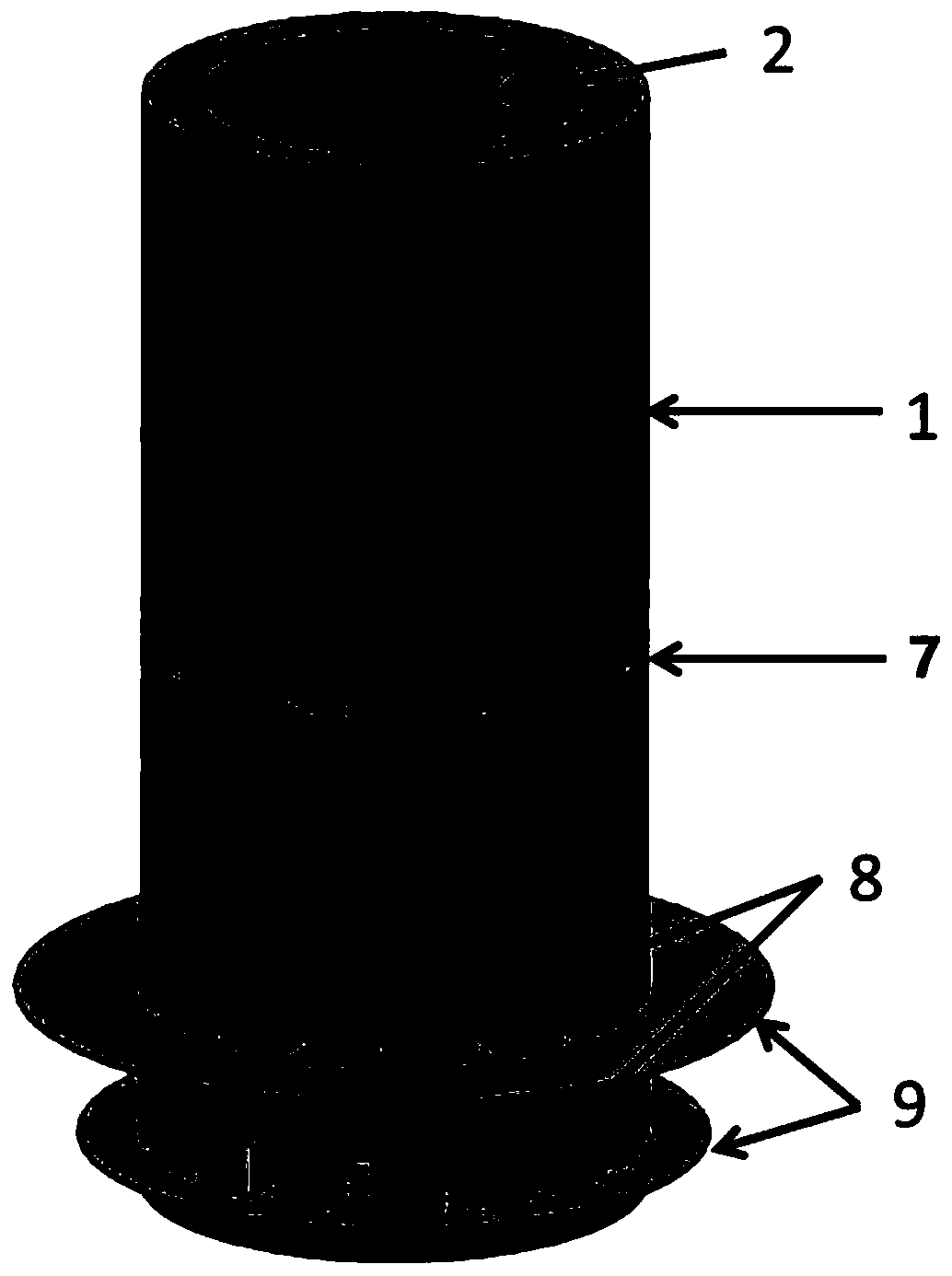
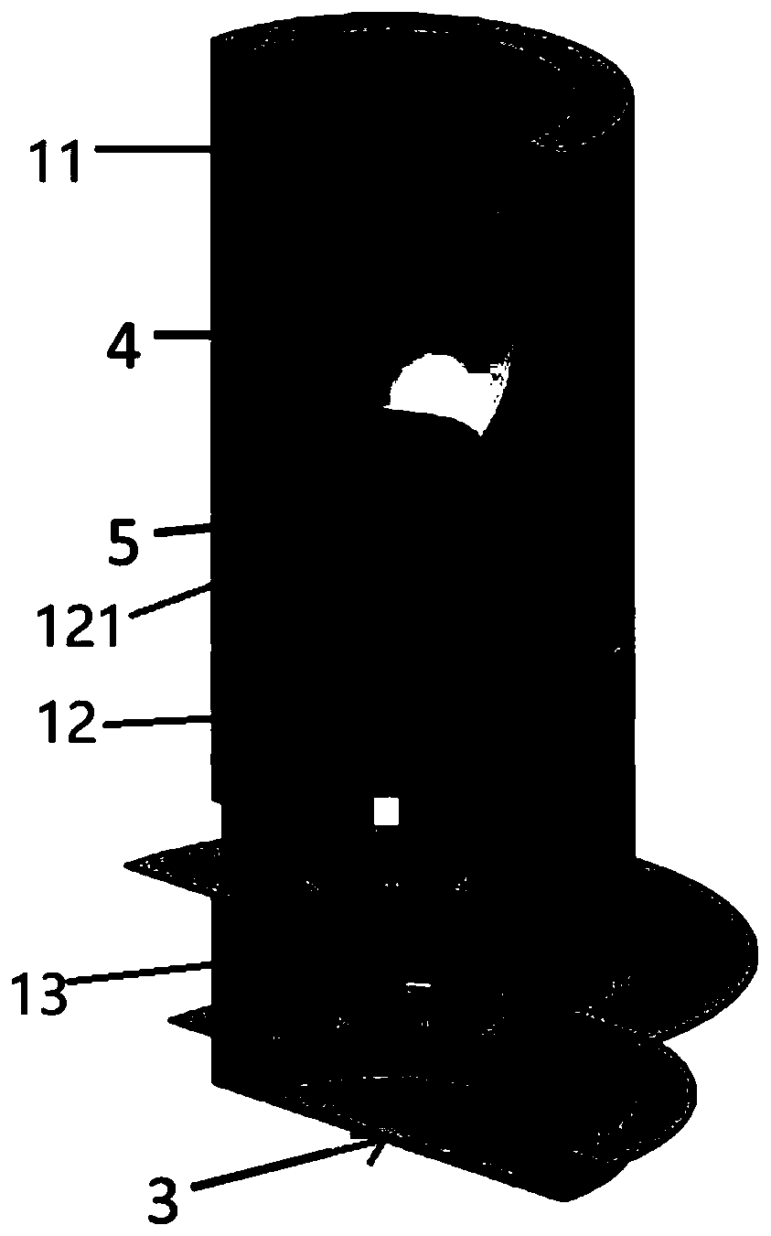
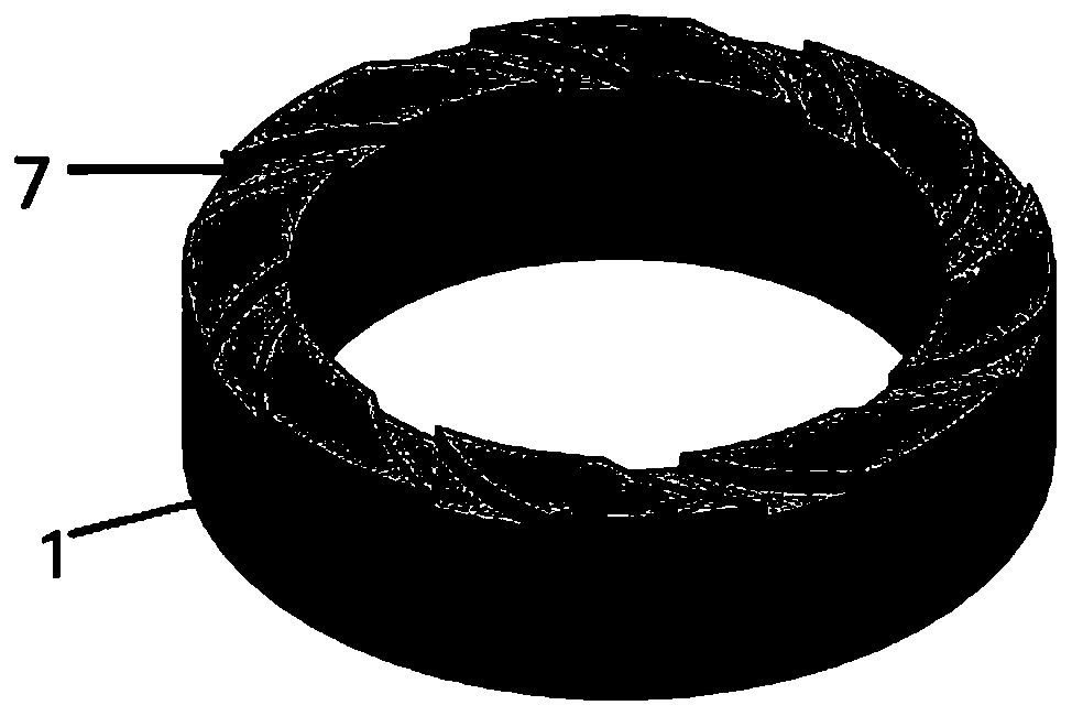
[0029] The sparger of the present invention was tested in a fixed bed reactor with a diameter of 1.0 m and a catalyst packing height of 1.0 m. The catalyst used is glass beads with a diameter of 0.5-1.2 mm. The liquid phase feed is tap water with a flow rate of 50 cubic meters per hour. The inner diameter of the distributor inlet is 150 mm, the inner diameter of the throat is 50 mm, and there are 6 suction ports and suction channels at the throat outlet. The ratio of the total flow cross-sectional area of ​​the suction port to the cross-sectional area of ​​the distributor inlet is generally 0.22. The lower part of the device is provided with three layers of distribution grooves, each layer has 16 grooves, all distribution grooves are rectangular, and the width is 14 mm, of which the height of the first layer of distribution grooves is 54 mm, the height of the second layer is 38 mm, and the height of the third layer is 30 mm. There are deflectors on the outside of each layer o...

Embodiment 2

[0033] Change the inner diameter of the throat of the distributor in Example 1 to 30 mm, and the exit of the throat is provided with 10 suction ports and suction passages, and the ratio of the total flow cross-sectional area of ​​the suction port to the cross-sectional area of ​​the distributor inlet is generally 0.5, The lower part of the distributor is provided with two layers of distribution grooves, each layer has 20 distribution grooves, and all distribution grooves are rectangular with a width of 14 mm. The height of the first layer of distribution grooves is 62 mm, and the height of the second layer is 25 mm. The outside of each layer of distribution grooves is provided with deflectors, which are flush with the bottom of the distribution grooves. The width of the first layer of deflectors is 75 mm, and the width of the second layer of deflectors is 40 mm.

[0034]Adopt above-mentioned sparger to repeat the process in embodiment 1, the result shows: within 5 seconds of sw...


PUM


Abstract

The invention relates to a feed distributor used in a fixed-bed reactor operated in full liquid phase, comprising a distributor cylinder, the cylinder comprising a feed zone, a mixing zone and a distribution zone from top to bottom, wherein the The top of the feeding area is the material inlet, and the feeding area and the mixing area are connected through a diameter-reducing structure and a throat in turn, and a plurality of suction channels are arranged on the side wall of the upper part of the mixing area. The bottom of the zone is provided with a blind plate, and the side wall is provided with a plurality of distribution grooves 8 distributed in the circumferential direction. The outer side of the distribution grooves is also provided with an annular deflector, and the deflector is arranged flush with the bottom end of the distribution groove. The invention can eliminate the dead zone that is easily formed in the cone angle area on the top of the reactor, makes the performance of the reactor closer to that of a plug flow reactor, and has the advantages of uniform liquid distribution, simple structure, and convenient manufacture and installation during use.

Description

technical field [0001] The invention belongs to the field of chemical industry and relates to a feed distributor, in particular to a feed distributor used in a fixed-bed reactor operated under full liquid phase conditions. Background technique [0002] Liquid distributors are widely used in various chemical equipment, and their main function is to disperse liquid materials evenly in the equipment space to meet the requirements of mass transfer, heat transfer or chemical reaction. Commonly used traditional liquid distributors mainly include pipe-type liquid distributors, orifice-plate liquid distributors, groove-disk liquid distributors, etc. [0003] For a fixed bed reactor operated in full liquid phase, the resistance of the liquid passing through the bed usually helps to obtain a better fluid distribution effect, and the main function of the liquid distributor is to reduce the influence of the inlet kinetic energy on the liquid distribution, and at the same time eliminate ...

Claims


Application Information

Patent Timeline
Patent Type & Authority Patents(China)
IPC IPC(8): B01J8/02
CPCB01J8/0278
Inventor 刘鹏乔小飞朱发明张晨陈雁玲林少宁于天勇
Owner WANHUA CHEM GRP CO LTD
Why Eureka
Try Eureka