
Multi-layer drop tube type falling film polycondensation reactor

A polycondensation reactor and reactor technology, applied in chemical/physical/physical chemical fixed reactors, chemical instruments and methods, chemical/physical/physical chemical processes, etc., can solve insufficient melt surface area, shaft sealing difficulties, Limited application and other issues, to achieve the effect of uniform residence time, tight arrangement of drop tubes, and accelerated transfer

Active Publication Date: 2016-09-21
ZHEJIANG UNIV
View PDF4 Cites 2 Cited by
  • Summary
  • Abstract
  • Description
  • Claims
  • Application Information

AI Technical Summary

Problems solved by technology

Both of these are horizontal stirred reactors, which rely on the lower part of the disc or mesh immersed in the melt layer to bring the melt into a film when rotating, but due to the influence of stirring, the energy consumption is relatively large, and Due to the high vacuum required in the system, it is relatively difficult to seal the shaft
At the same time, limited by the bridge of the melt grid in the kettle, on the one hand, the disk or mesh must maintain a large distance, resulting in insufficient surface area per unit melt, and on the other hand, the disk or mesh must have a certain distance from the inner wall of the kettle. distance to ensure no mechanical accidents, but there may be a certain dead zone
All of the above severely limit the application of these two reactors

Method used


Image

  • Multi-layer drop tube type falling film polycondensation reactor
  • Multi-layer drop tube type falling film polycondensation reactor
  • Multi-layer drop tube type falling film polycondensation reactor

Examples


Embodiment 1

[0031] Embodiment 1: PET final polycondensation process.

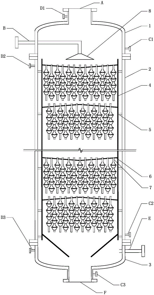
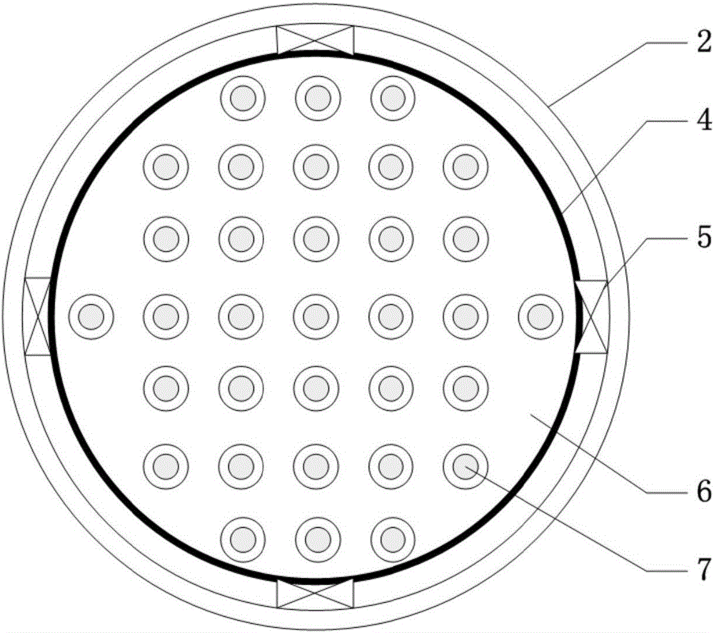
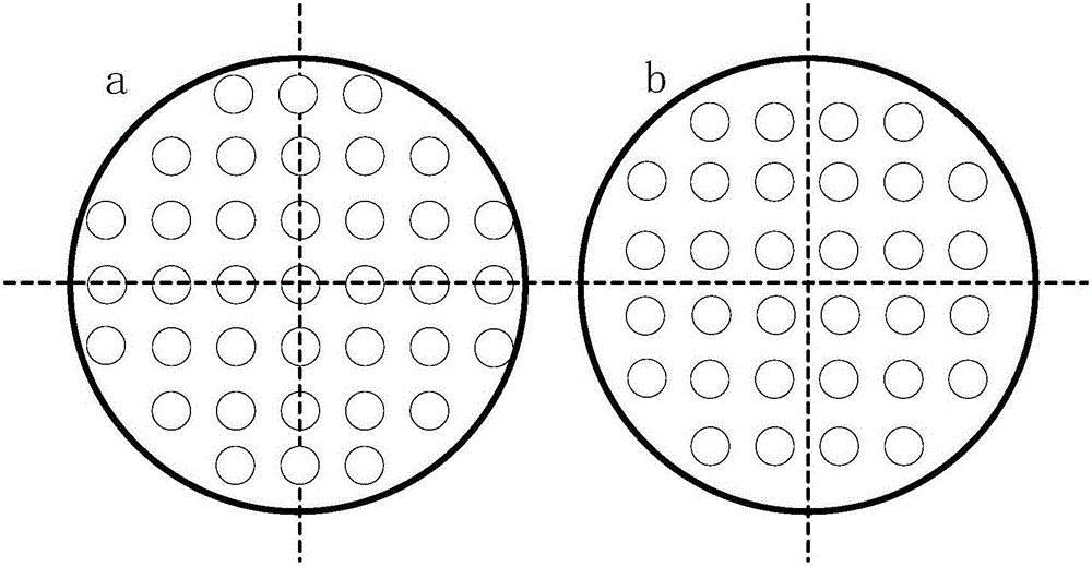
[0032] The structure and principle of the reactor are as above, and the structural parameters of some reactors are as follows: the number of openings is 10-100, the width of the leakage channel is 2-15mm, the vertical distance between two adjacent separation sleeves is 0-20mm, and the separation sleeve of each layer 5-20 pairs, the taper of the separation sleeve on the falling film falling tube is from 2:1 to 1:5, the bottom diameter of the separation sleeve is 30-200mm, and the number of layers is 10-30.

Embodiment 2

[0033] Example 2: Polymer devolatilization process.

[0034] The structure and principle of the reactor are as described above, and some structural parameters and operating parameters of the reactor are as follows: melt viscosity 10-100Pa·s, small molecule volatile content 2-5%, number of openings 10-100, leakage channel width 2 -10mm, the vertical distance between two adjacent separation sleeves is 0-10mm, 5-20 pairs of separation sleeves per layer, the taper of the separation sleeve on the falling film tube is from 2:1 to 1:5, and the bottom diameter of the separation sleeve is 30 -80mm, the number of layers is 10-30; compared with the smooth falling tube devolatilizer under the same structural parameters, the volatilization removal efficiency is increased by 25-35%.


PUM


Abstract

The invention relates to a multi-layer drop tube type falling film polycondensation reactor. The polycondensation reactor mainly comprises an outer tower and a plurality of tower cores arranged sequentially from top to bottom, wherein each tower core comprises a tower plate and a plurality of falling film drop tubes arranged side by side; each falling film drop tube comprises a hollow pipe and a plurality of drop sleeves fixed on the outer side wall of the hollow pipe; each drop sleeve comprises an upper separation sleeve and a lower separation sleeve. Depending on the action of gravity of materials, a very large gas-liquid phase interface is formed on the falling film drop tubes, and removal of small molecules is facilitated; when fluids pass through each pair of separation sleeves on each falling film drop tube, the fluid in an internal wall surface area and the fluid in a surface area exchange, and a good surface renewal effect is realized to increase the mass transfer rate. The reactor is simple in structure and high in surface renewal rate and has very large gas-liquid interface; the flow is large, and retention time is controllable; reaction energy consumption is low, and externally added power equipment is avoided.

Description

technical field [0001] The invention relates to a multilayer drop tube type falling film polycondensation reactor, in particular to a drop tube type polycondensation tower with a high specific interface. Background technique [0002] The characteristic of the polycondensation process is that through the reaction between the terminal functional groups, the small molecule products are gradually removed but the molecular weight of the polymer is gradually increased. For the whole reaction process, the viscosity of the system increases continuously with the progress of the reaction, with tens of milliPascal seconds and finally even reaching hundreds of thousands of milliPascal seconds. Especially in the later stage of the reaction, with the increase of viscosity and reaction degree, the removal of small molecules becomes very difficult, so mass transfer becomes the decisive factor controlling the progress of the reaction. Due to the extremely limited diffusion of small molecules...

Claims


Application Information

Patent Timeline
Patent Type & Authority Applications(China)
IPC IPC(8): B01J19/24B01J19/32
CPCB01J19/0053B01J19/247B01J19/32B01J2219/185B01J2219/322
Inventor 赵思维王嘉骏冯连芳顾雪萍刘钰余翔翔程层
Owner ZHEJIANG UNIV
Learn More