

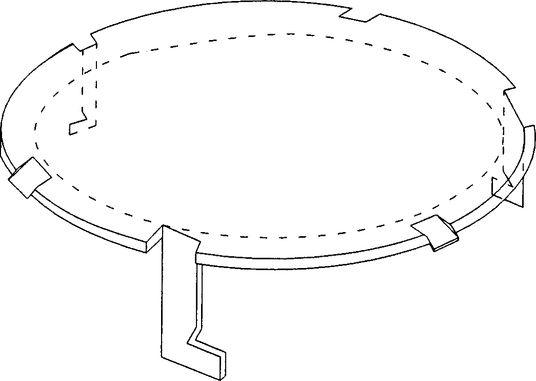
Three direction guided valve tower tray
A valve tray, three-direction technology, applied in distillation separation, chemical instruments and methods, separation methods, etc., can solve the problems of reduced tray efficiency, uneven distribution, reduced residence time, etc., to enhance mixing and exchange, increase Residence time, the effect of reducing foam entrainment
- Summary
- Abstract
- Description
- Claims
- Application Information
AI Technical Summary
Problems solved by technology
Method used
Image

Examples
Embodiment
[0032] The test tower with a diameter of 1.2mm has three trays inside, the lower layer is a gas distribution plate, the middle layer is a test plate, and the upper layer is a liquid entrainment collection plate. The test plate is three-guided 3-leg valve tray and F1 type valve tray. The technical parameters are as follows: the bow-shaped downcomer is 200mm wide, and the downcomer accounts for 11% of the tower cross section; the outlet weir is 890mm long, and the weir height is 50mm; the opening rate of the three-direction float valve is 17.7%; the air velocity is 0.8-3.6m / s; : 8~112m 3 / h;
[0033] A comparative test was carried out on two kinds of trays under the same conditions to measure their liquid foam entrainment rate, pressure drop and oxygen desorption efficiency. The comparative experimental data are as follows: Figure 9 , Figure 10 , Figure 11 and Figure 12 .
[0034] It can be seen from the above graph that the production capacity of the three-guided and ...
PUM
 Abstract
Description
Claims
Application Information