Heating device and magnetic recording head for thermally-assisted recording

a technology of magnetic recording head and heating device, which is applied in the field of heating device and magnetic recording head for thermally assisted recording, can solve the problems of insufficient power efficiency, thermal erasure of the application of heat spots significantly larger than the track width, and the realization of such systems, so as to increase the dwell time of heating and effective heating of the media

Inactive Publication Date: 2007-08-28
HITACHI GLOBAL STORAGE TECH NETHERLANDS BV
View PDF10 Cites 68 Cited by
  • Summary
  • Abstract
  • Description
  • Claims
  • Application Information

AI Technical Summary

Benefits of technology

[0015]In view of the foregoing problems and disadvantages of the conventional devices and methods, it is a purpose of the present invention to provide a heating device and a magnetic recording head which are suitable for realizing thermally-assisted magnetic recording (e.g., large area TAR) in order to improve on data storage densities of conventional magnetic recording. Another objective is to provide a heating device that can be implemented in an existing conventional (i.e., non-thermally-assisted) magnetic recording head. Another objective is to provide a magnetic recording head that realizes effective heating of the media by using a large-area heater which increases the dwell time for heating. Another objective is to provide a heating device and recording head which heat the recording medium on the leading edge side of the write gap, so as to synchronize the thermally-assisted recording process.
[0027]With its unique and novel features, the present invention provides an electrical heating device and a magnetic recording head for thermally-assisted recording which may be used, for example, for large-area TAR. As one of the key advantages the inventive heating device can be implemented in existing conventional (i.e., non-thermally-assisted) magnetic recording heads. The inventive magnetic recording head realizes effective heating of the media by using preferably a large-area heater, which increases the dwell time for heating. Further, the media is heated on the leading edge side of the write gap, which synchronizes the thermally-assisted recording process.

Problems solved by technology

However, while potential media materials with sufficiently high KU are known, this approach is limited to values of Hc lower than about half the maximum head write field in order for the head to be able to write to the media (e.g., see D. Weller, A. Moser, L. Folks, M. E. Best, W. Lee, M. F. Toney, J.-U.
Ultimately, however, any approach using a heat spot significantly larger than the track width will be limited by thermal erasure due to repeated heat exposure of adjacent data tracks during writing (e.g., see J. J. Ruigrok, R. Coehoorn, S. R. Cumpson, and H. W. Kesteren, “Disk recording beyond 100 Gb / in.2: Hybrid recording?”, J. Appl. Phys. 87, 5398 (2000)).
Earlier realizations of such systems suffered from insufficient power efficiencies and low data rates for writing and reading in all-optical systems (e.g., see E. Betzig, J. K. Trautman, T. D. Harris, R. Wolfe, E. M. Gregory, P. L. Finn, M. H. Kryder, C.-H.
However, in practice, it turns out that small-area TAR faces several major challenges, especially if a heater in the recording head is used to realize the heating.

Method used


Image

  • Heating device and magnetic recording head for thermally-assisted recording
  • Heating device and magnetic recording head for thermally-assisted recording
  • Heating device and magnetic recording head for thermally-assisted recording

Examples


Embodiment Construction

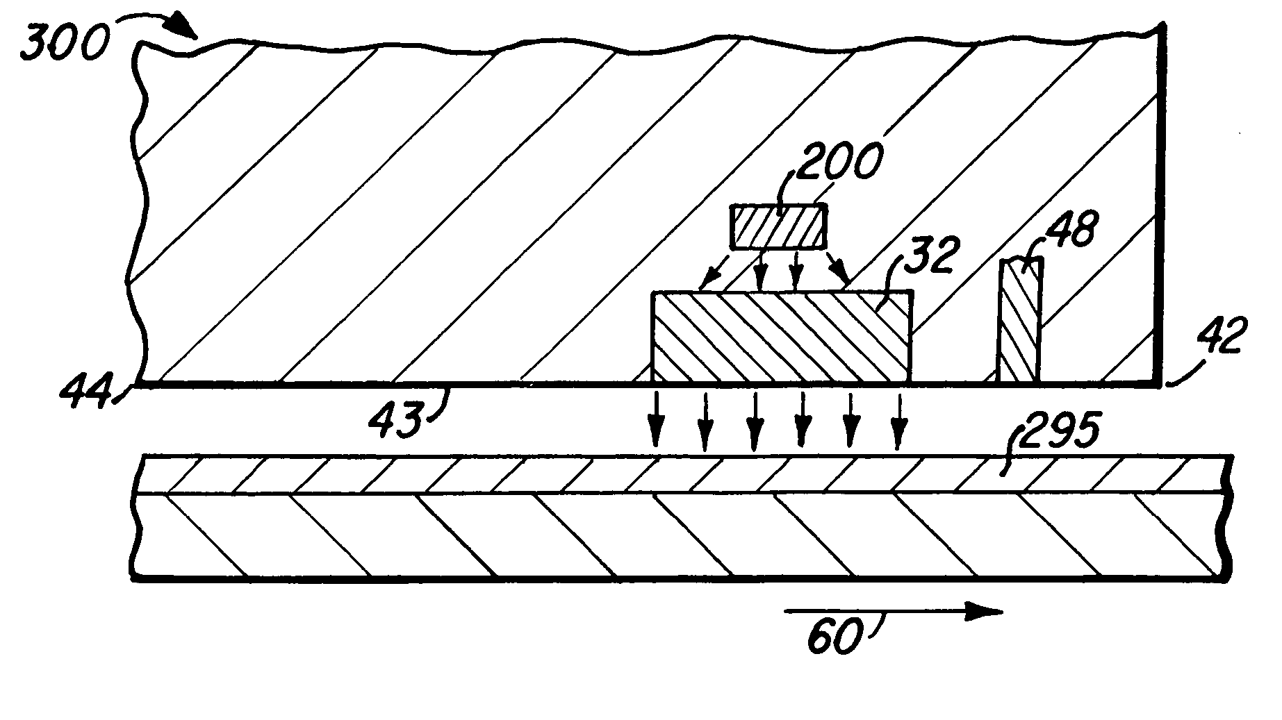
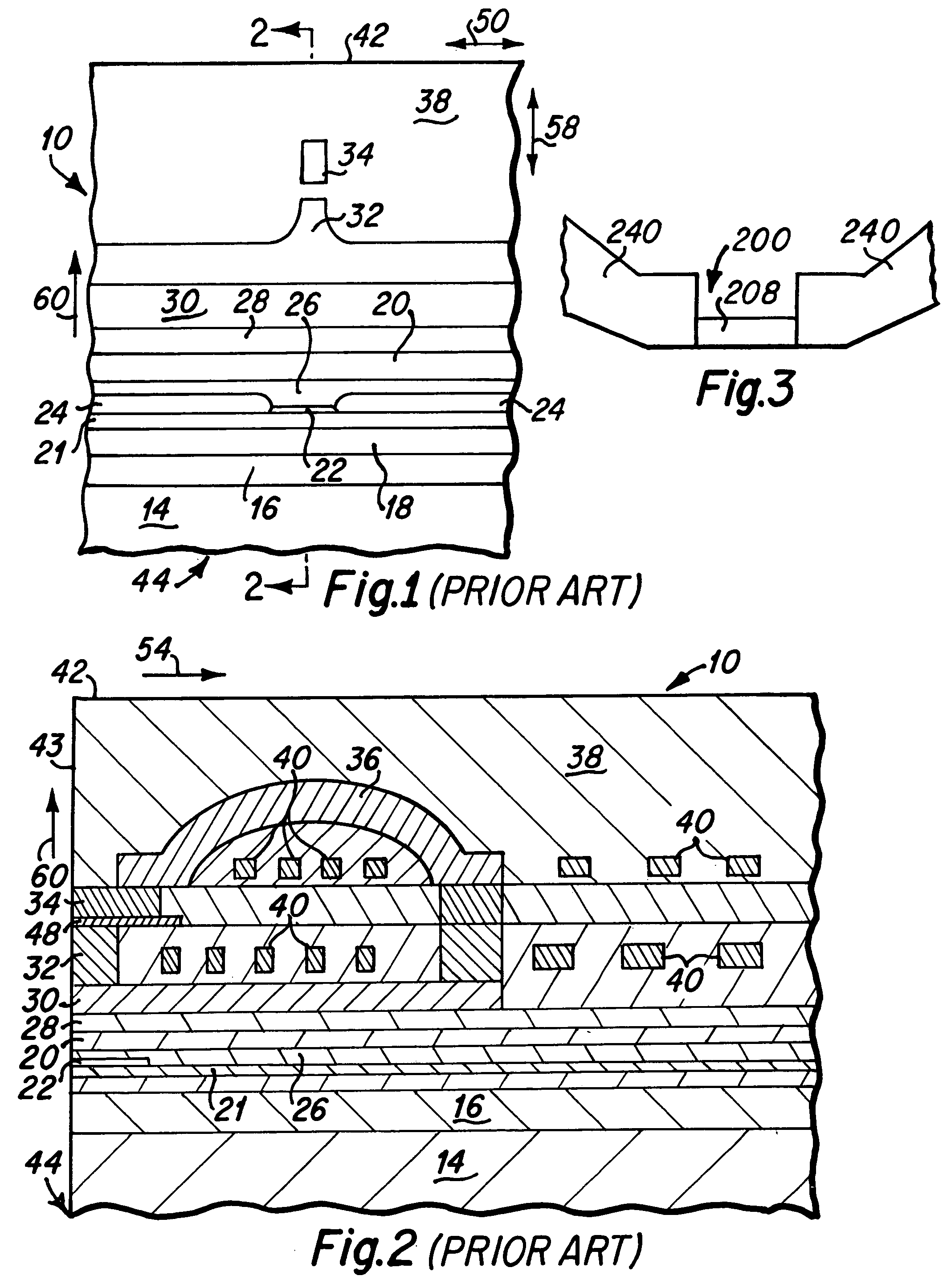
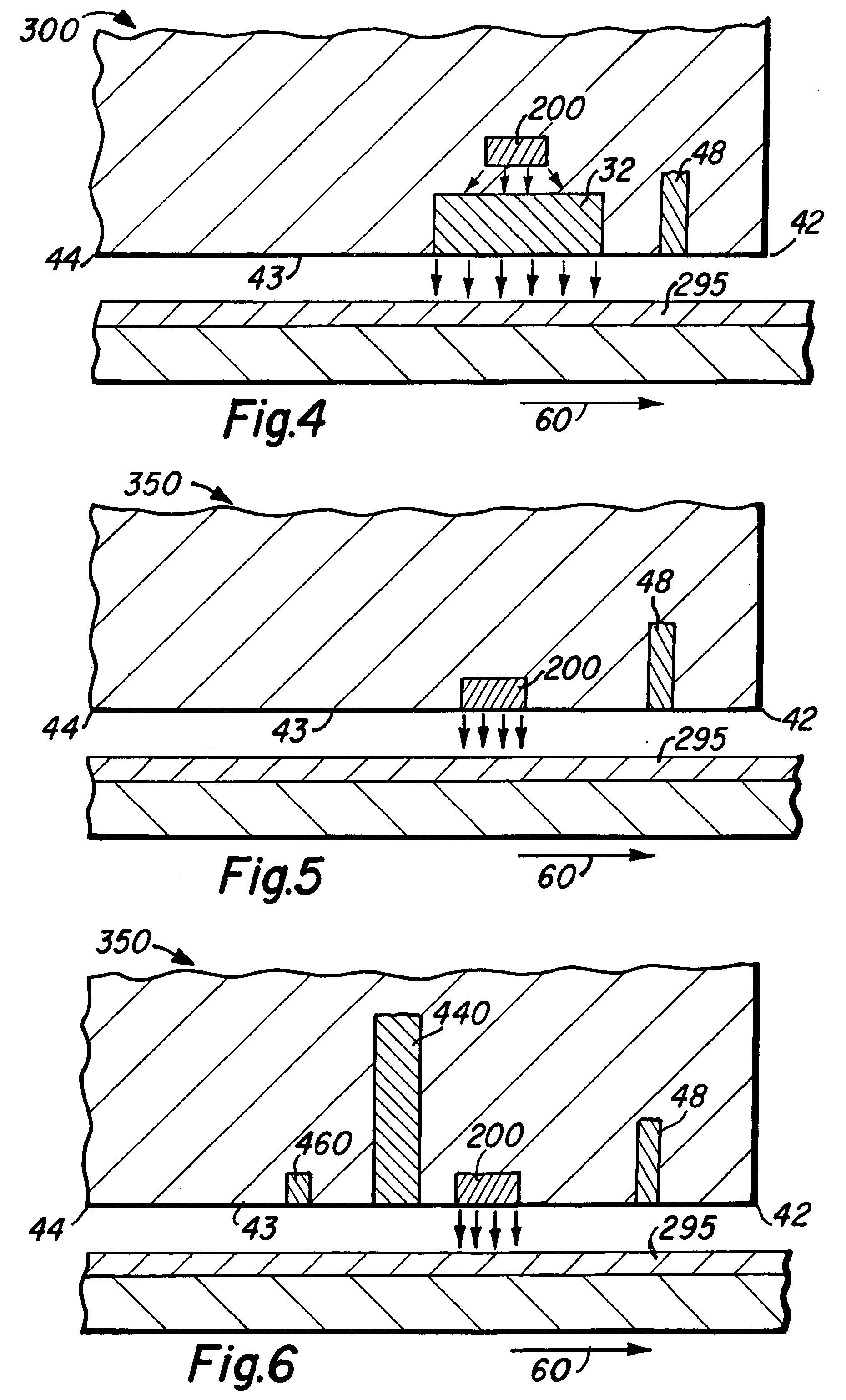
[0035]Referring now to the drawings, and more particularly to FIGS. 1 and 2, a typical magnetic recording head 10 includes a first magnetic pole layer having two members, a P1 pole layer 30 and a P1P pole pedestal 32, and a second magnetic pole tip P2 34. FIG. 3 illustrates an inventive heating device 200 for a magnetic recording head, and FIGS. 4-6 illustrate magnetic recording heads in which a heating device 200 may be used to heat (e.g., directly or indirectly) the recording medium 295.

[0036]Generally speaking, for purposes of this Application, the term “width” will refer to a dimension in an across track direction (FIG. 1, arrow 50), the term “height” or “stripe height” will refer to a dimension in a direction away from the ABS of the magnetic recording head (FIG. 2, arrow 54), and the term “thickness” will refer to a dimension in a down track direction (FIG. 1, arrow 58).

[0037]The present invention may be used, for example, for large-area thermally-assisted magnetic recording. ...


PUM

PropertyMeasurementUnit
widthaaaaaaaaaa
widthaaaaaaaaaa
thicknessaaaaaaaaaa

Abstract

A heating device for a magnetic recording head includes first and second separating layers, the first separating layer having preferably a higher or equal thermal resistance than the first separating layer, and a heater formed between the first and second separating layers. A magnetic recording head for recording on magnetic medium includes a heating device which generates a heat spot on the magnetic medium which is larger than a magnetic track width, and / or heats a portion of the magnetic recording head which is on a leading edge side of a write gap in the magnetic recording head.

Description

BACKGROUND OF THE INVENTION[0001]1. Field of the Invention[0002]The present invention generally relates to a heating device and a magnetic recording head for thermally-assisted recording, and more particularly, a heating device and magnetic recording head which may be used for large-area thermally-assisted recording.[0003]2. Description of the Related Art[0004]In longitudinal magnetic disk recording, scaling to higher areal densities has historically relied on a continuous reduction of the magnetic grain size and the width of the grain size distribution in the recording media in order to keep media noise within acceptable limits. In contrast, the number of magnetic grains per bit cell has been reduced only slowly (e.g., see M. F. Doerner, K. Tang, T. Arnoldussen, H. Zeng, M. F. Toney, and D. Weller, “Microstructure and thermal stability of advanced longitudinal media”, IEEE Trans. Mag. 36, 43 (2000)).[0005]The reduction of the average grain size has in turn led to a reduction of the...

Claims


Application Information

Patent Timeline
Patent Type & Authority Patents(United States)
IPC IPC(8): G11B5/00G11B5/127
CPCG11B5/127G11B2005/0005G11B2005/0021
Inventor HAMANN, HENDRIK F.KASIRAJ, PRAKASHLILLE, JEFFREY S.MARTIN, YVES C.POON, CHIE CHINGROBERTSON, NEIL LESLIETHIELE, JAN-ULRICHWICKRAMASINGHE, HEMANTHA KUMAR
Owner HITACHI GLOBAL STORAGE TECH NETHERLANDS BV
Why Eureka
Try Eureka