Method and apparatus for maldi analysis

a laser desorption and ionization mass spectrometry technology, applied in the field of matrix assisted laser desorption/ionization mass spectrometry, to achieve the effect of broadening the tof peak width and increasing the residence tim

Inactive Publication Date: 2002-01-17
AGENA BIOSCI
View PDF0 Cites 63 Cited by
  • Summary
  • Abstract
  • Description
  • Claims
  • Application Information

AI Technical Summary

Benefits of technology

[0012] In other embodiments, a thermalizing region is defined by a small ferrule or capillary-like tube enclosure which surrounds a region at the end of the illumination fiber. The matrix is deposited along the inner cylindrical wall of the tube, where the divergent fiber output illuminates the matrix. The tube provides a short tunnel as a migration path to the outlet in which the desorbed material is initially ejected with oblique paths for thermalization of the desorbed analyte. In other embodiments microstructures having the shape of a small lean-to, overhang or perforated cover plate provide containment to increase residence time or provide collisional interaction for thermalization of the released analyte. Such a confining microstructure can also be formed by the sample crystals and the surface of the substrate if the crystallization process is specifically controlled to achieve such structures.
[0013] The latter constructions may include a two stage release configuration wherein the laser illumination forms a plume which then fills a compartment. The compartment has an opening in one wall through which the thermalized ions which have migrated from the illumination plume are emitted. In this two-stage construction, the distance between illumination and outlet is made large enough to thermalize the large molecules, but small enough to assure that emission of analyte ions occurs in a short time interval that does not broaden the TOF peak width.

Problems solved by technology

Emission from the source then illuminates the sample, causing the analyte to be desorbed at a surface of the plate facing the mass analyzer assembly.

Method used


Image

  • Method and apparatus for maldi analysis
  • Method and apparatus for maldi analysis
  • Method and apparatus for maldi analysis

Examples


Embodiment Construction

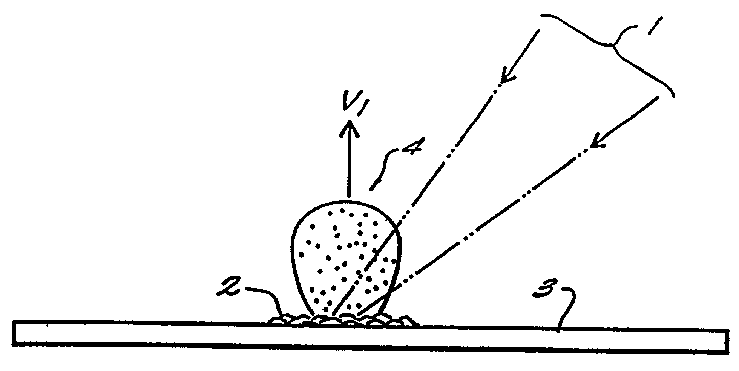
[0030] FIG. 1 shows a representative prior art set up for the matrix assisted laser desorption and ionization of a specimen such as a large molecule compound having a molecular weight, for example, in the range of 500 to 100,000 daltons or more. As shown, a substrate 3 such as a sheet of metal foil or a glass slide, bears a sample 2 in a region on its surface. As discussed above, sample 2 is generally deposited as a solution of a relatively low molecular weight laser-absorbent material with a minor amount of the large molecule analyte contained therein, and it is allowed to dry in place to form a thin layer of solid material which may for example consist of a granular or continuous bed of crystals. In special cases a solvent, stable in vaccuo is used such as glycerol. The sample 2 then forms a thin liquid layer or droplet on substrate 3. A laser beam 1 is directed at the sample 2 causing a plume 4 of material to be desorbed therefrom. In general, the matrix material is taken to be a...


PUM

PropertyMeasurementUnit
molecular weightaaaaaaaaaa
velocityaaaaaaaaaa
diameteraaaaaaaaaa

Abstract

Matrix assisted laser desorption / ionization is performed in a manner to thermalize large analyte ions in a plume of desorbed material for spectroscopic analysis. The thermalized ions have a low or zero mean velocity and are presented at a well-defined instant in time, reducing artifacts and sharpening the spectral peaks. In one embodiment the light is delivered to a matrix or sample holder having a cover, baffle or compartment. The baffle or compartment impedes or contains a plume of desorbed material and the analyte undergoes collisions to lower its mean velocity and directionality. Thus "thermalized" the analyte ions are passed to a mass analysis instrument. In a preferred embodiment an optical fiber butts up against a thin transparent plate on which the specimen resides, with the matrix side in a vacuum acceleration chamber. A mechanical stage moves the specimen in both the x- and y- directions to select a point on the specimen which is to receive the radiation. The use of a fiber optic illuminator allows the entire stage assembly to be subsumed essentially within the dimensions of a conventional stage. In other embodiments, a thermalizing compartment is provided in a capillary tube about the end of the illumination fiber and the sample matrix is deposited along the inner cylindrical wall of the tube, so the capillary forms a migration path to the outlet for thermalization of the desorbed analyte. In other embodiments microstructures having the shape of a small lean-to, overhang or perforated cover plate, or providing a high aspect surface texture, provide the necessary containment to promote thermalization of the released analyte. A thin layer or cover of fibrous or permeable material may also be used to thermalize the analyte before mass analysis, and in other embodiment this material may also act as the substrate. An automated instrument may include a fixed array of illumination fibers which are illuminated at different times to eject samples from a corresponding array of points on the specimen.

Description

RELATED APPLICATIONS[0001] This application is a continuation of U.S. application Ser. No. 08 / 934,455, filed Sep. 19, 1997, which is a continuation-in-part of U.S. application Ser. No. 08 / 710,565, filed Sep. 19, 1996, now U.S. Pat. No. 5,777,324, each of which is incorporated herein by reference in its entirety.BACKGROUND[0002] The present invention relates to Matrix Assisted Laser Desorption / Ionization Mass Spectrometry (MALDI-MS). This method introduced by Karas and Hillenkamp in 1988 has become established as a method for mass determination of biopolymers and substances such as peptides, proteins and DNA fragments. In this method, the substance to be analyzed is typically placed in a solution of matrix material and coated onto a support. The solute evaporates, leaving the analyte in a solid matrix which is then illuminated to cause the analyte molecules or synthetic polymers to be desorbed. This desorption process is especially useful for releasing large biological molecules with...

Claims


Application Information

Patent Timeline
Patent Type & Authority Applications(United States)
IPC IPC(8): B01D59/44C40B60/14G01N27/62G01N27/64H01J49/00H01J49/04H01J49/10H01J49/16
CPCB01J2219/00387C40B60/14H01J49/0418H01J49/164
Inventor HILLENKAMP, FRANZLOUGH, DAVID M.HIGGINS, G. SCOTTREUTER, DIRK
Owner AGENA BIOSCI
Why Eureka
Try Eureka