

Apparatus and method for a gas turbine entrainment system
a technology of entrainment system and gas turbine, which is applied in the direction of mechanical equipment, machines/engines, lighting and heating apparatus, etc., can solve the problems of inability to achieve sufficient combustion mixing, inefficiency, operability problems and/or reliability issues, etc., to achieve the effect of facilitating turbulence and/or mixing and reducing losses
Active Publication Date: 2009-07-16
SPYTEK AEROSPACE CORP
View PDF18 Cites 56 Cited by
- Summary
- Abstract
- Description
- Claims
- Application Information
AI Technical Summary
Benefits of technology
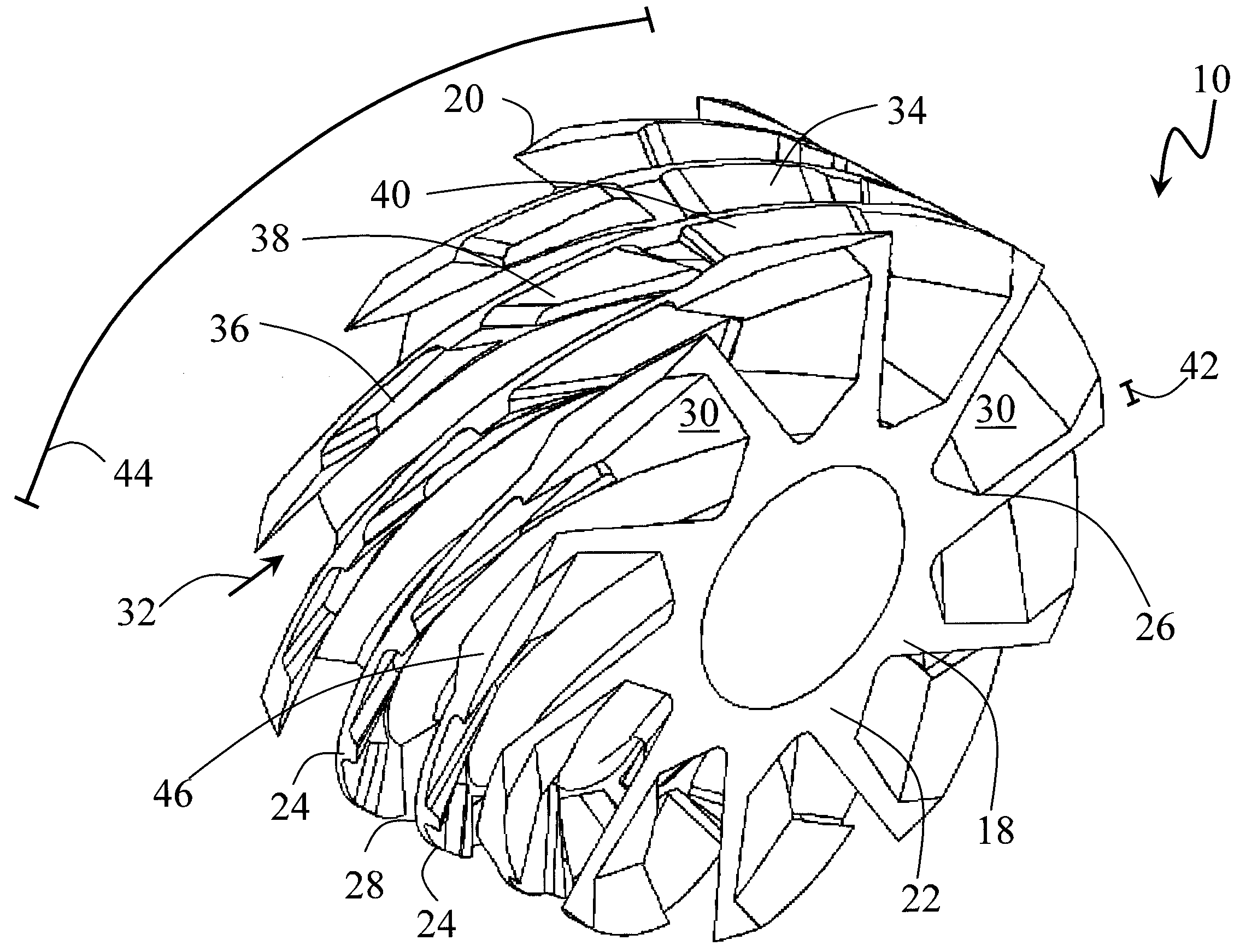
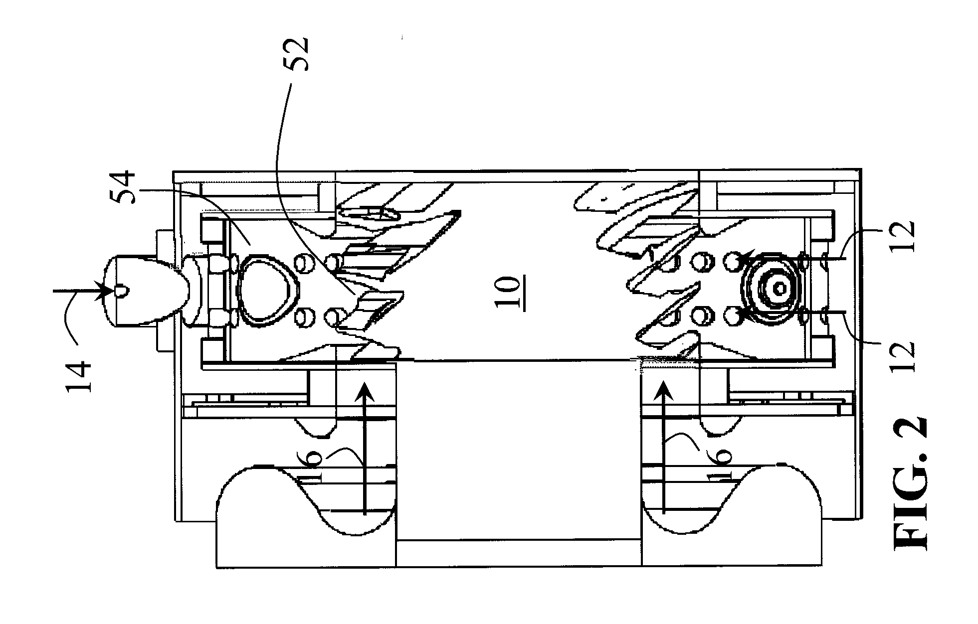
[0011]The helical flow path increases the residence time of the non-combustion gases under the burner and allows increased mixing resulting in a more uniform temperature profile before the turbine section. The angle of the helical flow path from an axis of the axial body includes any suitable sharp angle, bend or change in direction. An effective length of the helical flow path may include a multiple of the axial length of the axial body.
[0013]A profile or cross section of each trench has as a canted V-shape at the tip and widens into a parallelogram shape at the root, and a width of each trench increases along a length of each helical vane from the first end of the axial body to the second end of the axial body, to reduce losses and according to one embodiment of this invention. Each trench may include a tilt of a suitable angle to further facilitate turbulence and / or mixing.
Problems solved by technology
Insufficient mixing of the combustion products and the cooling air results in unfavorable temperature gradients reaching the turbine section causing thermal stresses, inefficiencies, operability problems and / or reliability issues.
However, these short designs may not allow sufficient mixing of the combustion products and the cooling air to result in efficient and reliable turbine operation.
Known mixing systems employ a primarily axial orientation for the dilution air resulting a less than optimal mixing since the mixing length is based on the short width of the burner.
Method used
View moreImage
Smart ImageViewing Examples

Examples
example
[0059]During tests of an embodiment of entrainment system 10, the following results were observed: 1) successful drawdown of hot gasses occurs within all three of the radial cavities 34 on the high pressure side of the entrainment vanes 24, 2) successful drawdown of gases along the low pressure side of vane 24 starts at about 30% of length 44 and is completely drawn down to the low pressure side blade root by the 65% length point and 3) during rig tests a hot gas stream occurs at the entrainment exit root.
Login to View More PUM
 Abstract
This invention relates to an apparatus for an entrainment system of a vortex burning combustion chamber or a vortex burning inter-turbine burner in a gas turbine. The entrainment system rapidly and thoroughly mixes hot combustion gases with non-combustion gases to reduce the gas temperature before entering a turbine. The entrainment system includes a plurality of helical vanes forming trenches and resulting in a highly helical flow path. The highly helical flow path provides an increased residence time for mixing of the combustion gases and non-combustion gases. Radial cavities in the helical vanes, canted vane angles and varying geometries further facilitate mixing while reducing losses. This invention also includes a method of mixing combustion and non-combustion gases in an entrainment system.
Description
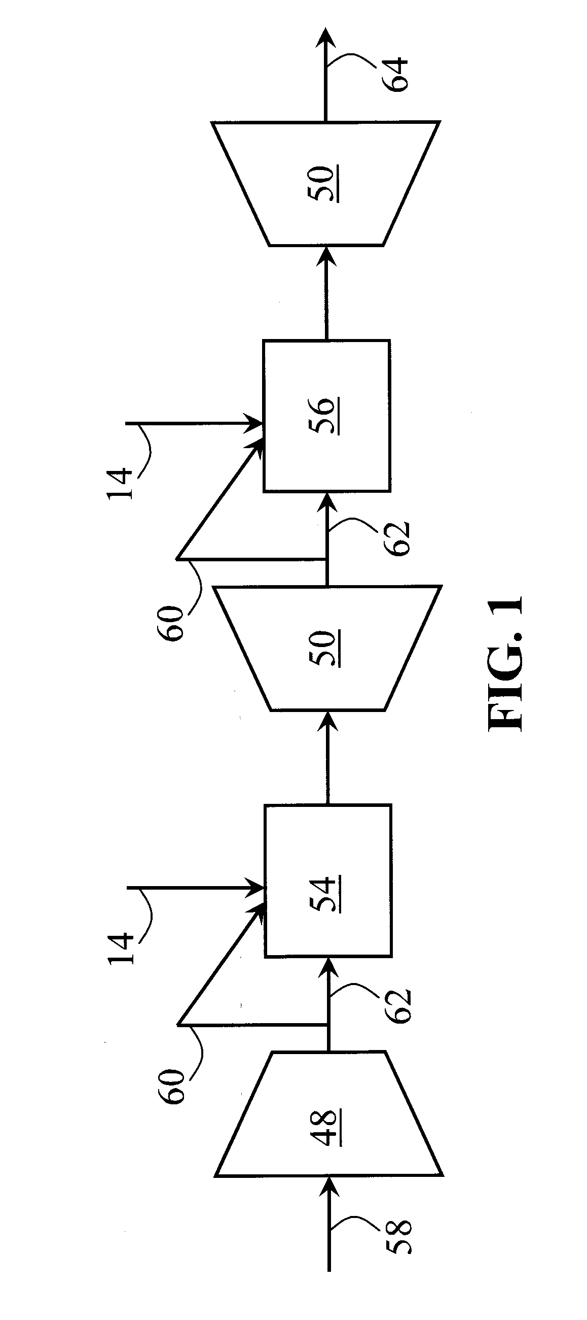
BACKGROUND OF THE INVENTION[0001]1. Field of the Invention[0002]The present invention relates to an entrainment system for mixing combustion gases and non-combustion gases in vortex burning gas turbine engines.[0003]2. Discussion of the Related Art[0004]Gas turbines include an air compressor section, a burner section and a turbine section. The compressed air from the air compressor is split with a part used for combustion of the fuel and a part used to cool the combustion products down to a temperature compatible with the materials of construction of the turbine section. Insufficient mixing of the combustion products and the cooling air results in unfavorable temperature gradients reaching the turbine section causing thermal stresses, inefficiencies, operability problems and / or reliability issues.[0005]Developments in gas turbines have led to vortex burning combustion chambers and vortex burning inter-turbine burners. Vortex burning devices may offer increased power, increased effic...
Claims
Login to View More Application Information
Patent Timeline
 IPC IPC(8): F02C1/00F02C3/14
CPCF02C3/14F02C6/003F23M9/08F05D2260/2212Y02T50/676F05D2260/60F05D2250/25F23R3/58Y02T50/60
Inventor SPYTEK, CHRISTOPHER J.
Owner SPYTEK AEROSPACE CORP