Method and device for carrying out fluid identification by using converted transverse wave earthquake data

A technology for transforming shear wave and seismic data, applied in the field of fluid identification, can solve problems such as lack of research

Inactive Publication Date: 2012-05-09
中国石化集团胜利石油管理局有限公司
View PDF5 Cites 0 Cited by
  • Summary
  • Abstract
  • Description
  • Claims
  • Application Information

AI Technical Summary

Problems solved by technology

[0003] However, there is still a lack of similar studies on continental sandstone and mudstone reservoirs

Method used


Image

  • Method and device for carrying out fluid identification by using converted transverse wave earthquake data
  • Method and device for carrying out fluid identification by using converted transverse wave earthquake data
  • Method and device for carrying out fluid identification by using converted transverse wave earthquake data

Examples


Embodiment 1

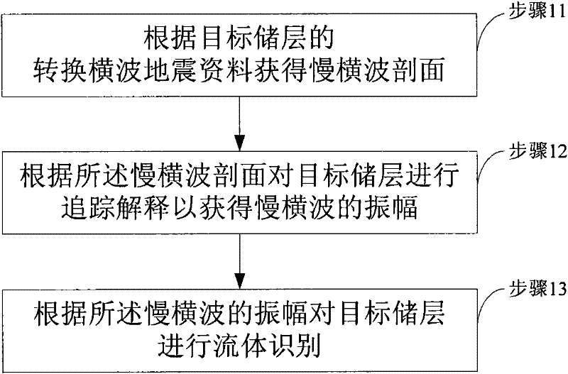
[0039] figure 1 It is a flow chart of a method for fluid identification using converted shear wave seismic data provided by Embodiment 1 of the present invention. Such as figure 1 As shown, the method includes:

[0040] Step 11, obtaining a slow shear wave profile according to the converted shear wave seismic data of the target reservoir;

[0041] Step 12, tracking and interpreting the target reservoir according to the slow shear wave profile to obtain the amplitude of the slow shear wave;

[0042] Step 13, performing fluid identification on the target reservoir according to the amplitude of the slow shear wave.

[0043] Among them, the fluid identification based on the amplitude of the slow shear wave is mainly analyzed based on the magnitude of all the obtained amplitudes. When the magnitude of the amplitude is above the middle value, it is an oil and gas area, otherwise it is a water injection area or a water flooded area.

Embodiment 2

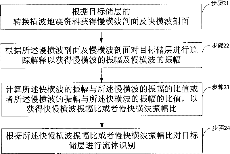
[0045] figure 2 A flow chart of a method for fluid identification using converted shear wave seismic data provided in Embodiment 2 of the present invention, the method includes:

[0046] Step 21, obtaining a slow shear wave profile and a fast shear wave profile according to the converted shear wave seismic data of the target reservoir;

[0047] Step 22. Tracking and interpreting the target reservoir according to the slow shear wave profile and the fast shear wave profile to obtain the amplitude of the slow shear wave and the amplitude of the fast shear wave;

[0048] Step 23, calculating the ratio of the amplitude of the fast shear wave to the amplitude of the slow shear wave or the ratio of the amplitude of the slow shear wave to the amplitude of the fast shear wave to obtain the amplitude ratio of the fast and slow shear waves or the amplitude ratio of the slow and fast shear waves;

[0049] Step 24: Perform fluid identification in the target reservoir according to the amp...

Embodiment 3

[0064] Figure 8 Embodiment 3 of the present invention provides a device for fluid identification using converted shear wave seismic data. Such as Figure 8 As shown, the device includes:

[0065] a slow shear wave profile acquisition unit, configured to obtain a slow shear wave profile according to the converted shear wave seismic data of the target reservoir;

[0066] A slow shear wave amplitude acquisition unit, configured to track and interpret the target reservoir according to the slow shear wave profile to obtain the amplitude of the slow shear wave;

[0067] The fluid identification unit is configured to identify the fluid of the target reservoir according to the amplitude of the slow shear wave.

[0068] Wherein, the slow shear wave amplitude acquisition unit traces and interprets the target reservoir according to the slow shear wave profile to obtain the amplitude of the slow shear wave, and then the fluid identification unit performs fluid identification according...


PUM


Abstract

The invention discloses a method for carrying out fluid identification by using converted transverse wave earthquake data, which comprises the following steps: A, acquiring a slow transverse wave section according to the converted transverse wave earthquake data of a target storage layer; B, tracking and explaining the target storage layer according to the slow transverse wave section to acquire the amplitude of slow transverse wave; and C, carrying out the fluid identification for the target storage layer according to the amplitude of the slow transverse wave. The invention also discloses a device for carrying out the fluid identification by using the converted transverse wave earthquake data. The method and the device have the advantages that the method and the device can effectively forecast the distribution of oil, gas and water in sand shale oil-gas reservoirs according to the amplitude of the slow transverse wave.

Description

technical field [0001] The invention belongs to the field of seismic data interpretation, in particular to a method and device for fluid identification using converted shear wave seismic data. Background technique [0002] Converted shear wave seismic data come from multi-wave and multi-component seismic acquisition, which can be used to study the anisotropy of fractured oil and gas reservoirs and detect fracture development zones. When the shear wave enters the fracture, it splits into two mutually perpendicular waves due to the splitting of the shear wave. One wave propagates along the fracture with a faster speed and is called a fast wave; the other wave propagates perpendicular to the fracture with a slower speed and is called a slow wave. Therefore, information such as the width, density and direction of fractures can be delineated by using slow waves to provide better data for oilfield development. [0003] But there is still a lack of similar research on continental ...

Claims


Application Information

Patent Timeline
Patent Type & Authority Patents(China)
IPC IPC(8): G01V1/28G01V1/32
Inventor 毕丽飞张永刚石建新李九生刘丽媛
Owner 中国石化集团胜利石油管理局有限公司
Why Eureka
Try Eureka