Drawing in machine

A drawing-in machine and threading technology, applied in the field of drawing-in machines, can solve problems such as difficult to find heald faults, complicated work to eliminate faults, complicated procedures and heald transmission

Inactive Publication Date: 2009-12-30
TOYOTA IND CORP
View PDF1 Cites 14 Cited by
  • Summary
  • Abstract
  • Description
  • Claims
  • Application Information

AI Technical Summary

Problems solved by technology

Therefore, the procedure of operation and transfer of healds is complicated
[0012] (4) Since a plurality of healds are fixed by the gear belt at the position where they are conveyed to the support, it...

Method used


Image

  • Drawing in machine
  • Drawing in machine
  • Drawing in machine

Examples


Embodiment Construction

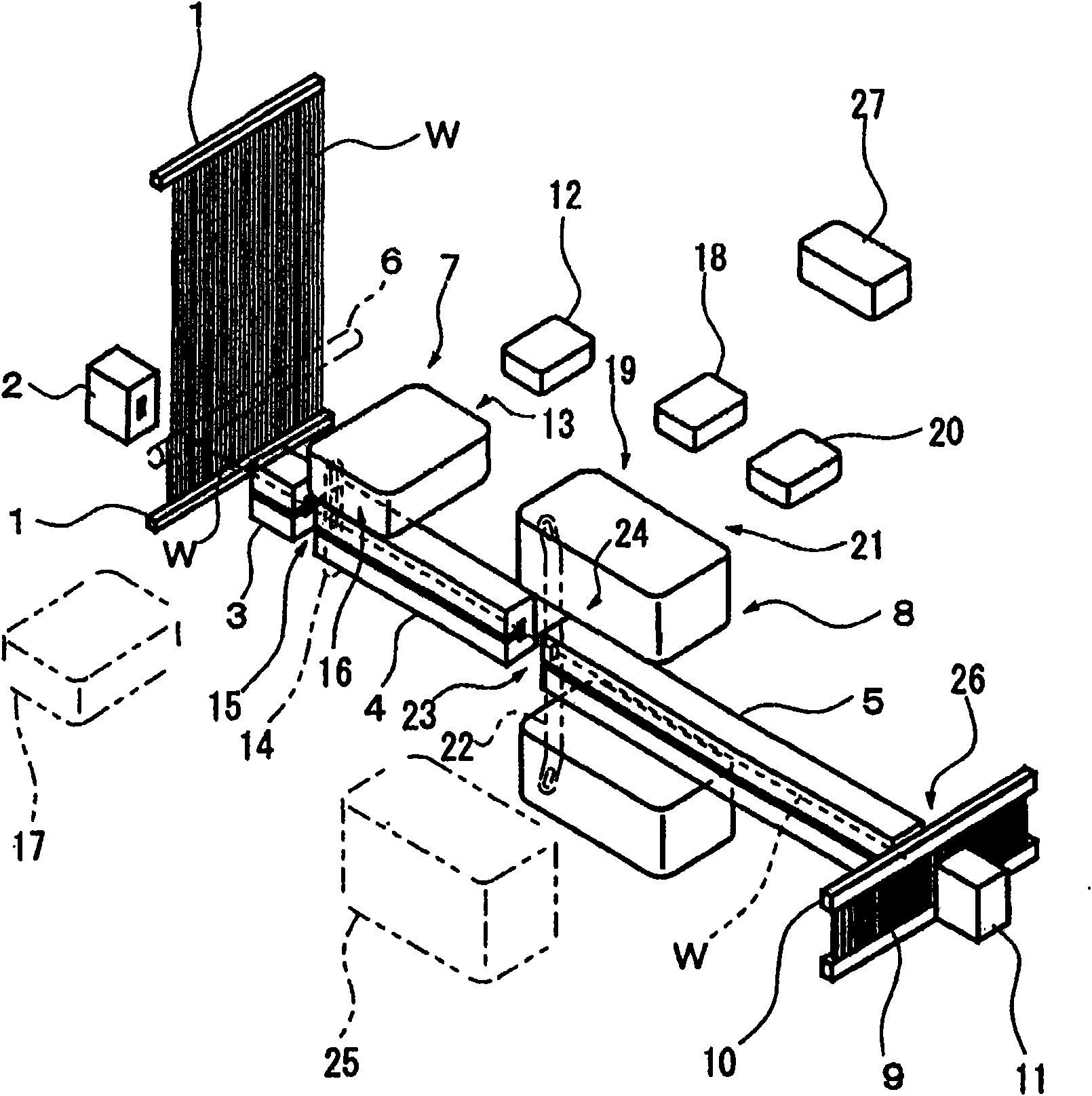
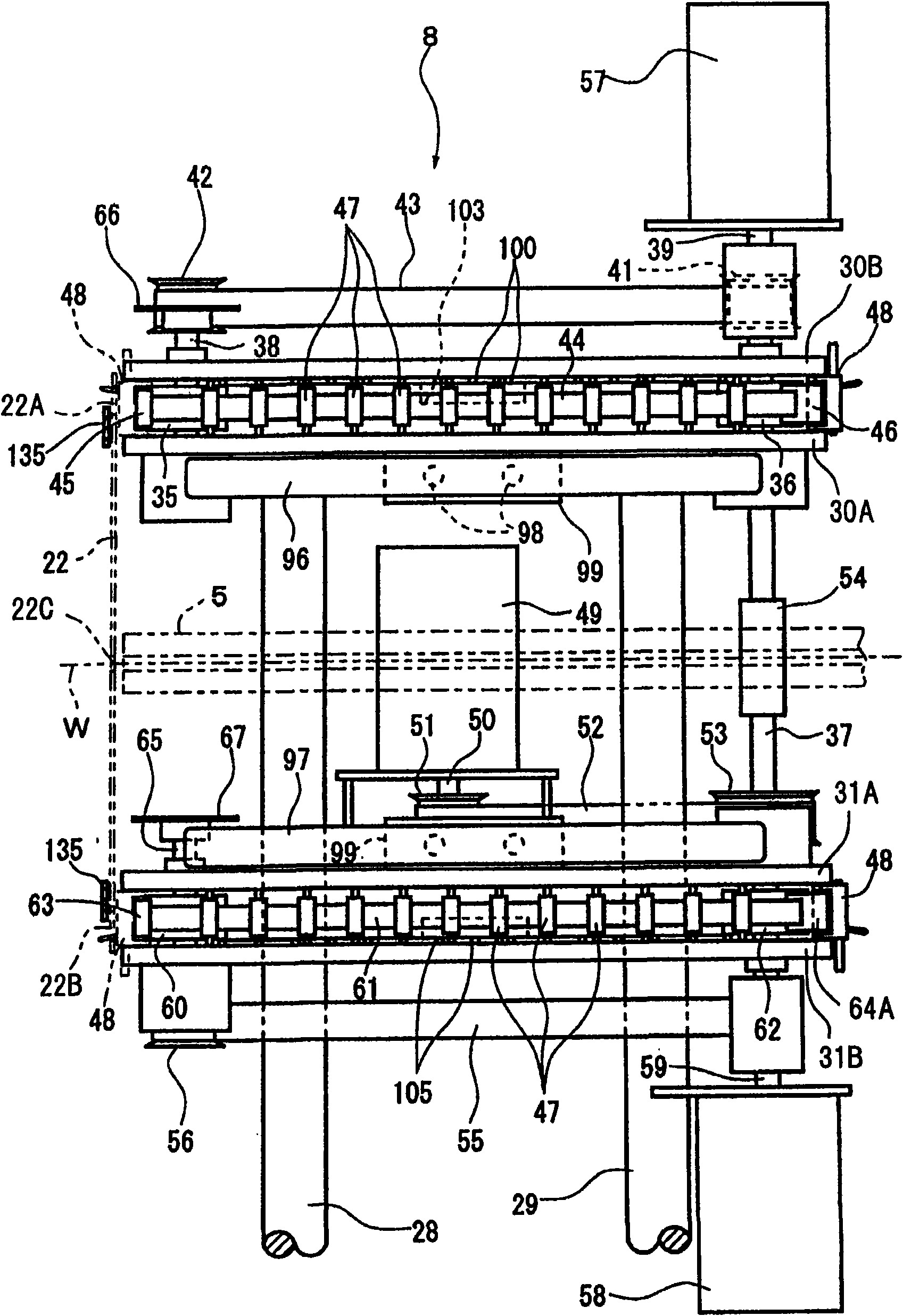
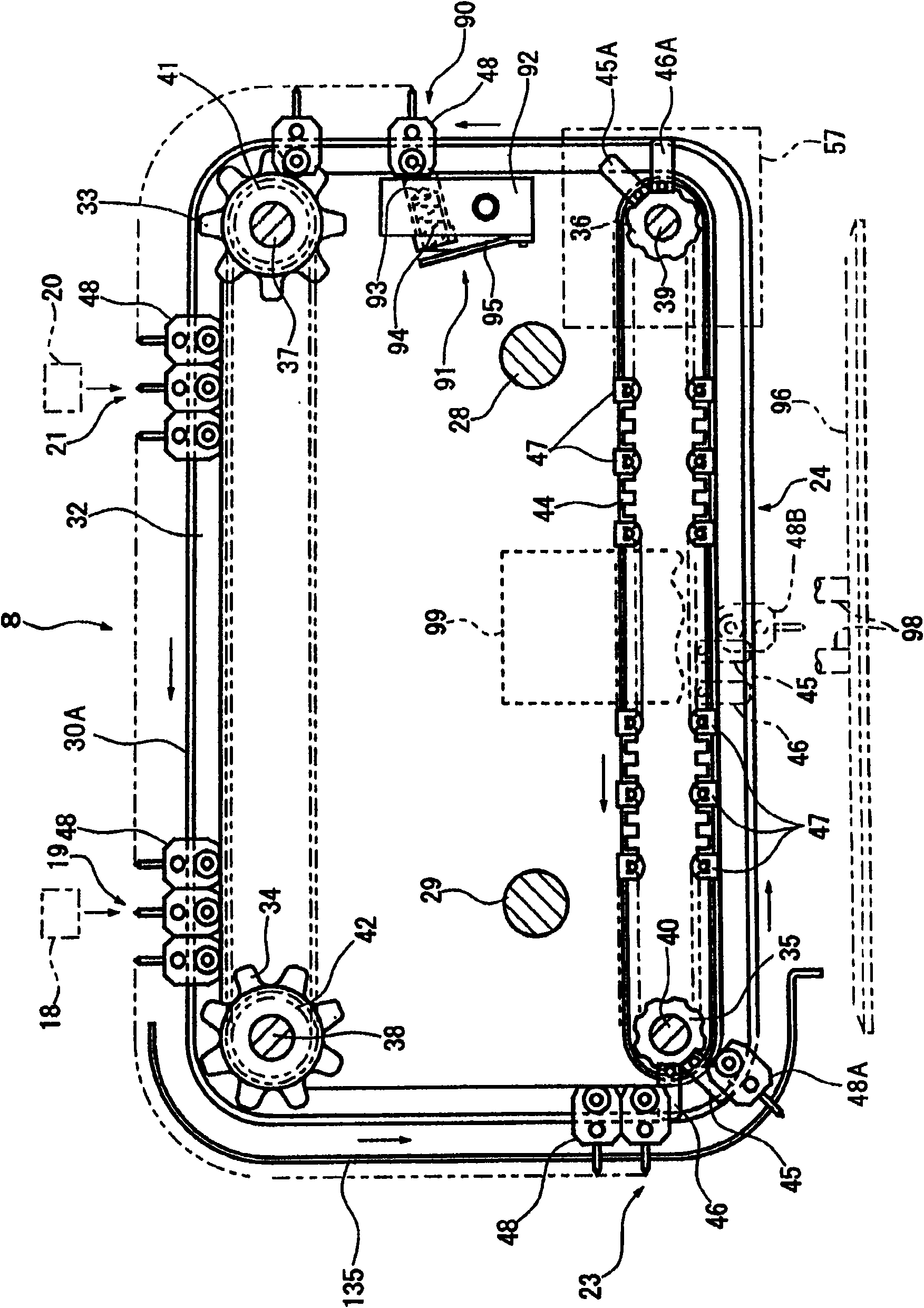
[0028] The following will refer to the attached Figures 1 to 8 A first preferred embodiment of the present invention will be described. First, refer to the attached figure 1 A drawing-in machine according to a first preferred embodiment of the present invention will be described. The nozzles 2 and the guide members 3, 4, 5 are arranged in a straight line on both sides of a plurality of warp yarns W drawn from a warp beam (not shown) and clamped in the clamping frame 1 . A guide rod 6 is provided between the nozzle 2 and the warp yarn W. As shown in FIG. The dropper conveying mechanism 7 is provided on the upper portion of the flow guide member 4 . The heald conveying mechanism 8 has a pair of conveying members provided on the upper and lower sides of the flow guide member 5, respectively. A reed 10 having a plurality of reed teeth 9 spaced apart from each other at a small pitch is arranged perpendicularly to the ends of the flow guide members 5 . A reed spacer 11 with a ...


PUM


Abstract

A drawing in machine comprises a plurality of laths, a lath memory and a transporting mechanism. The transporting mechanism receives the laths separated from the lath memory at the heddle supplying position, and transports the heddle to the warp leading position, and transports to the lath popping position through the lath led with warps. The transporting mechanism comprises a plurality of loaders, loader guides, transporting mechanisms of constant pitch and transporting mechanisms of non-constant pitch. The loaders fix the independent lath and can be movably arranged on the loader guides. The loader guides lead the loader having lath to the warp leading position. The transporting mechanisms of constant pitch transport the loader from the heddle supplying position to the warp leading position by instant pitch. The transporting mechanisms of non-constant pitch transport the loader from the warp leading position to the lath popping position by instant pitch.

Description

technical field [0001] The present invention relates to a drawing-in machine for threading warp yarns through a harness, such as a heddle or dropper, and more particularly to the transfer of the harness from a harness feed position to a harness ejection position. Background technique [0002] Japanese Patent No. 3213813 discloses a heald transmission mechanism for automatically threading warp yarns through heddles in a drawing-in machine. [0003] The drawing-in machine disclosed in the above-mentioned patent has a heald transfer device for operatively transferring a heddle, such as a heald, between a first position where the heald is separated from its storage device and a second position where the warp thread passes through the heddle. [0004] The transfer device has a pair of top and bottom plates spaced apart from each other by a predetermined distance, a gear belt is arranged around the plates, chain links are also arranged around the plates, and four guide wheels are ...

Claims


Application Information

Patent Timeline
IPC IPC(8): D03J1/14
CPCD03J1/14
Inventor 森下寿男
Owner TOYOTA IND CORP
Why Eureka
Try Eureka