Eureka AIR delivers breakthrough ideas for toughest innovation challenges, trusted by R&D personnel around the world.

Start-up compound burner for water-coal-slurry or coal dust gasification furnace

A technology of coal water slurry and coal powder, which is applied in the direction of combined combustion mitigation, gas fuel burner, burner, etc., can solve the problems of low utilization rate of equipment and devices, reduced service life of refractory bricks, and long time for dealing with flameout accidents, etc. Achieve the effects of remote, timely and rapid processing, saving space and compact structure

Inactive Publication Date: 2011-04-13
YANKUANG GRP CO LTD +1
View PDF0 Cites 0 Cited by
  • Summary
  • Abstract
  • Description
  • Claims
  • Application Information

AI Technical Summary

Problems solved by technology

This is an operation method currently used in industrialized devices. The disadvantage of this method is that it takes a long time to deal with flameout accidents and the labor intensity is high.
Under the original oven conditions, this temperature that cannot change according to the heating curve will reduce the service life of refractory bricks
[0005] When the water-cooled wall pulverized coal gasifier is started, use the start-up burner to raise the temperature of the gasifier to a certain temperature to feed the coal powder. At this time, the start-up burner cannot be removed due to the temperature and pressure in the furnace. Therefore, many water-cooled The start-up burners, ignition guns, and fire detection devices of the wall gasifier device are all set separately, which not only causes low utilization rate of some equipment and devices, but also increases the expenditure

Method used


Image

  • Start-up compound burner for water-coal-slurry or coal dust gasification furnace
  • Start-up compound burner for water-coal-slurry or coal dust gasification furnace

Examples


Embodiment Construction

[0033] The following examples are used to illustrate the present invention, but are not intended to limit the scope of the present invention.

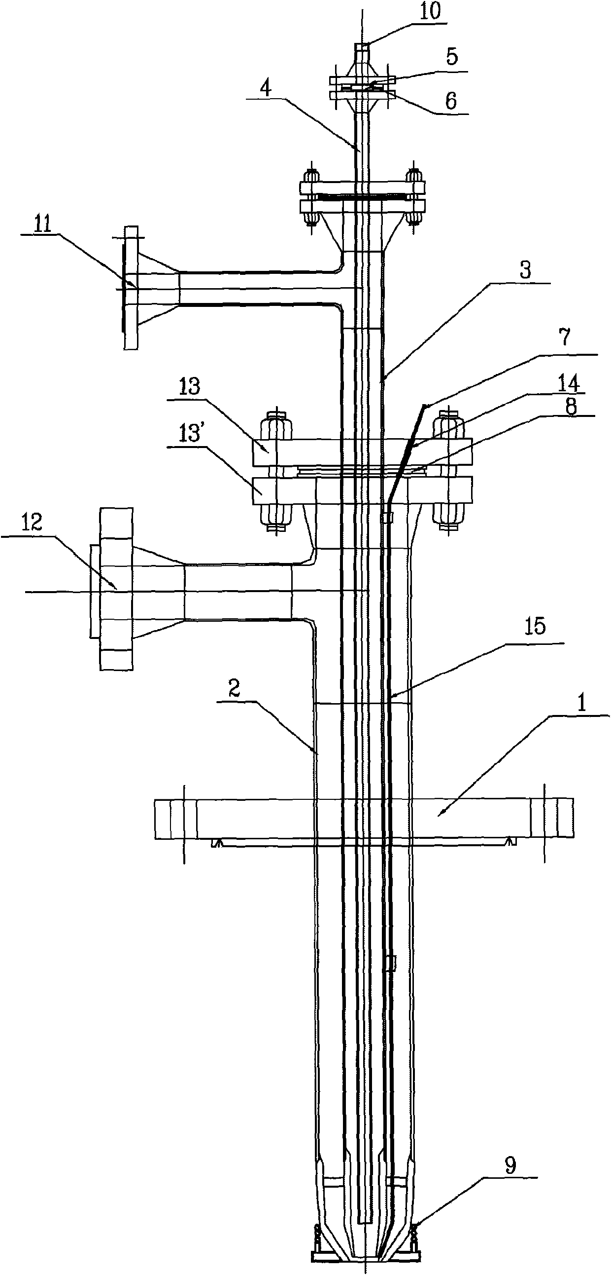
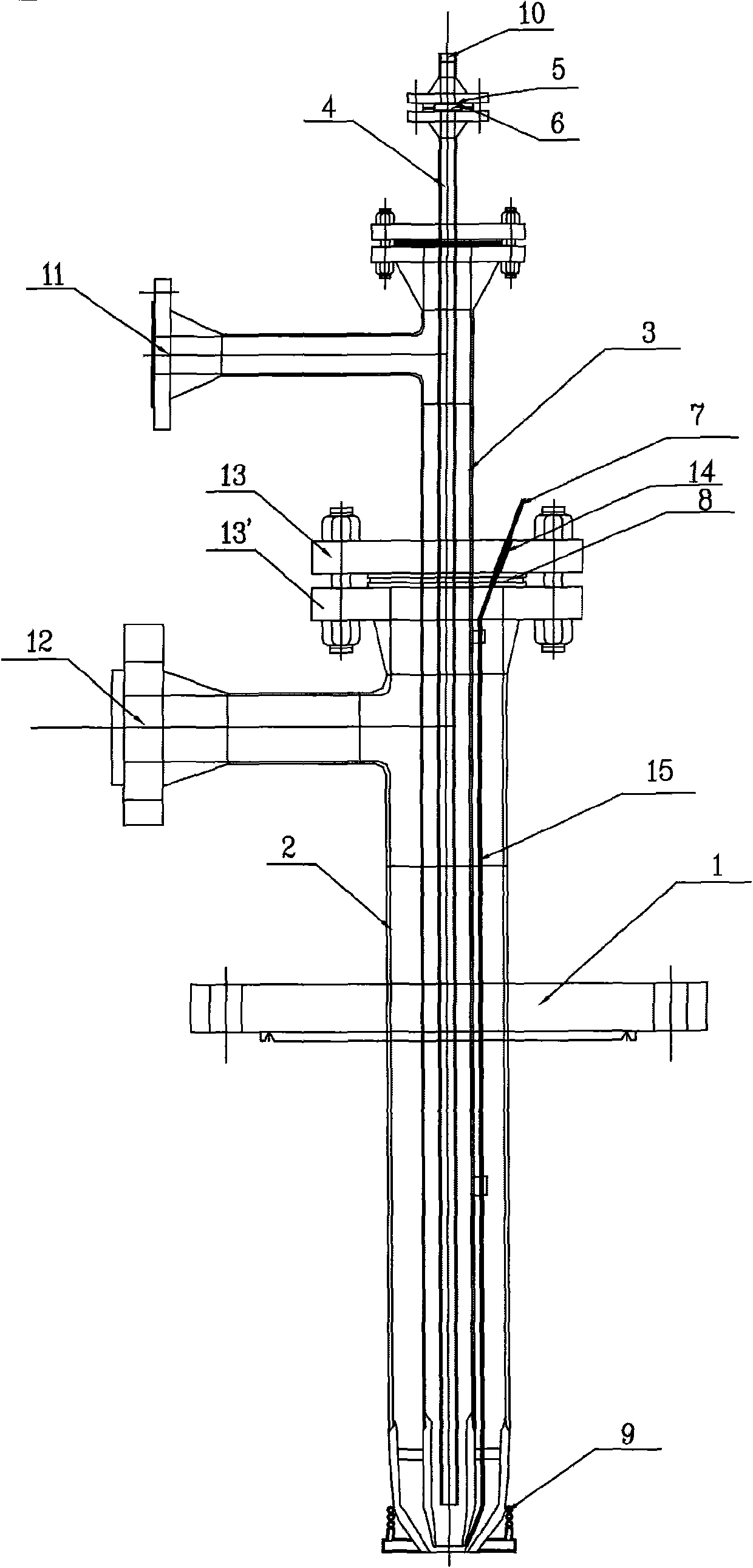
[0034] Such as figure 1 As shown, the composite burner of the gasification furnace of the present invention is connected to the gasification furnace through the installation flange 1 . Open a hole in the center of the mounting flange 1 and weld the fuel gas channel pipe 2. The fuel gas channel pipe connects to the fuel gas inlet 12 through the flange. A combustion-supporting gas channel pipe 3 is installed in the fuel gas channel pipe 2. The installation method is through two The flanges 13 and 13' are connected, and the combustion-supporting gas passage pipe 3 must maintain coaxiality with the fuel gas passage pipe 2 during welding and installation. The front ends of the fuel gas passage pipe 2 and the combustion-supporting gas passage pipe 3 are closed.

[0035] The general fuel gas of the gasifier is coal gas, synthetic gas or liq...


PUM


Abstract

The invention provides a start-up compound burner for a water-coal-slurry or coal dust pressure gasification furnace. The start-up compound burner comprises a fuel gas passage pipe and a combustion-supporting gas passage pipe which are coaxially sheathed with each other and respectively arranged inside and outside, and ignition electrodes, wherein the fuel gas passage pipe is connected with the combustion-supporting gas passage pipe through two flanges, the two flanges are sealed by a gasket, the size of an annular space between a flow passage at the front end of the combustion-supporting gaspassage pipe and the fuel gas passage pipe is adjusted by the thickness of the gasket, and the ignition electrodes are arranged outside the combustion-supporting gas passage pipe and extended to the front ends of the fuel gas passage pipe and the combustion-supporting gas passage pipe. The start-up compound burner has the advantages of compact structure and space saving. The burning of various fuel gases can be realized by adjusting the fuel gas passage. During the actual operation, the burner can automatically ignite and keep temperature rise stable. Besides, the invention can also lower thework intensity of on-site personnel, and can perform continuous operations of baker and chemical industrial feeding without being dismantled after the installation in cold conditions.

Description

technical field [0001] The invention relates to a pressurized gasification device for coal water slurry or pulverized coal, in particular to a composite burner for starting a pressurized gasification furnace for coal water slurry or pulverized coal. Background technique [0002] Coal gasification technology is a technology that can efficiently and cleanly utilize coal. At present, it has become one of the leading technologies for solving environmental pollution problems in all countries in the world, and it is also an important field of international competition. In the coal pressurized gasifiers that have been industrialized in various countries in the world, the different types of composite burners used in the start-up process have their own advantages and disadvantages. [0003] The key equipment of coal water slurry or pulverized coal pressurized gasification technology is the gasifier, and the gasifier must use a start-up burner when it is started. Taking the new coal-...

Claims


Application Information

Patent Timeline
Patent Type & Authority Patents(China)
IPC IPC(8): F23D14/00F23D14/46F23D14/78C10J3/72
CPCY02E20/18
Inventor 郭宝贵张鸿林路文学李磊郭军金刚傅进军
Owner YANKUANG GRP CO LTD
Why Eureka
Eureka Blog
Learn More