

UHF reader demodulation circuit
A technology of demodulation circuit and reader-writer, which is applied in the direction of instrument, diode modulation transformation, computer components, etc., can solve the problem of low mixing voltage gain of demodulation circuit of uhf reader-writer, so as to improve the receiving sensitivity and solve the problem of The effect of low gain
- Summary
- Abstract
- Description
- Claims
- Application Information
AI Technical Summary
Problems solved by technology
Method used
Image

Examples
Embodiment Construction
[0012] The present invention will be described in detail below with reference to the accompanying drawings.
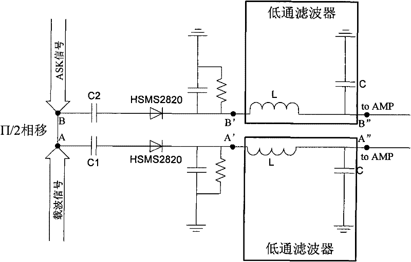
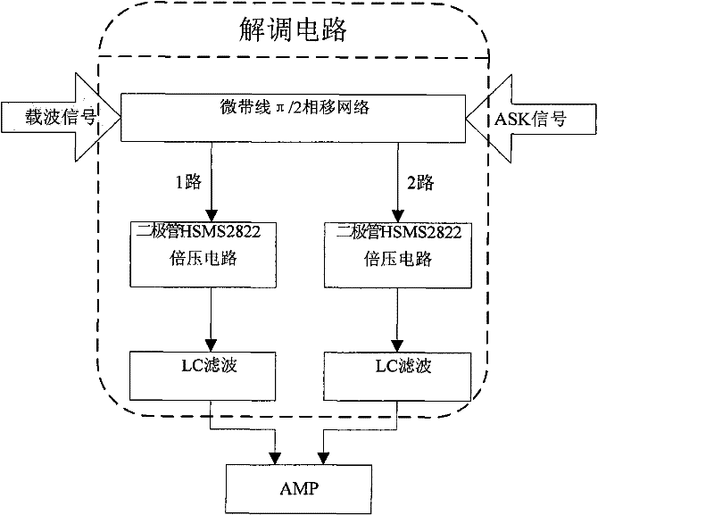
[0013] like figure 2 As shown, the present invention includes a 50-ohm microstrip line, two diode mixing circuits and two LC low-pass filters. The radio frequency signal will have a phase shift through the microstrip line, and the phase shift is determined by designing the length of the microstrip line. In the present invention, the impedance of the microstrip line is 50Ω, the input carrier signal and the ASK signal pass through the microstrip line to generate a phase shift of π / 2, and then go through two diode mixing circuits for frequency mixing, and finally pass through two LC low The carrier signal is filtered out by a pass filter and then output to the differential amplifier.
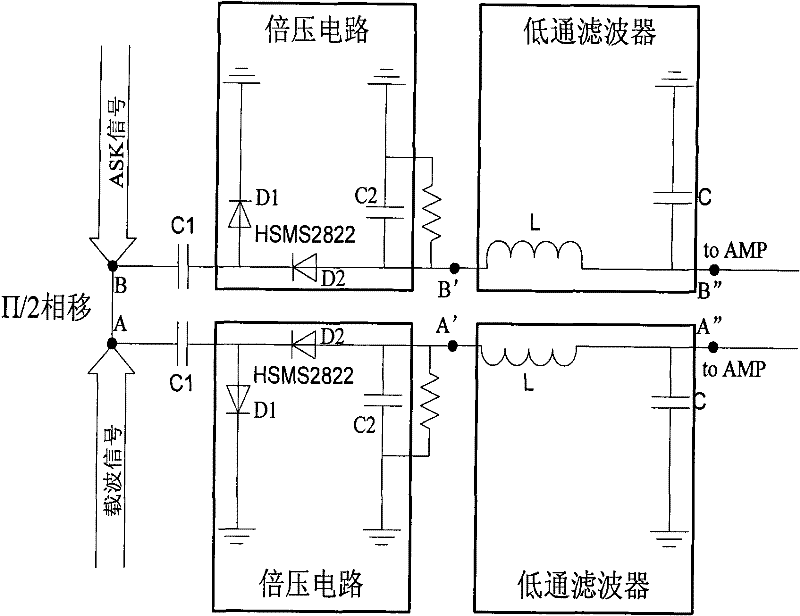
[0014] image 3 This is a circuit diagram of an embodiment of the passive demodulation circuit of the uhf reader / writer of the present invention. In this embodiment, the voltage doubling...
PUM
 Abstract
Description
Claims
Application Information