Demodulation method of multi-core fiber Bragg grating curvature sensor

A technology of curvature sensor and multi-core optical fiber, which is applied in the direction of converting sensor output, using optical devices to transmit sensing components, instruments, etc., can solve the problems of high demodulation cost and complex demodulation methods of spectrum analyzers, and achieve demodulation mode Simplification, reduction of demodulation cost, and strong scalability

Active Publication Date: 2017-08-18
SOUTHWEST JIAOTONG UNIV
View PDF6 Cites 7 Cited by
  • Summary
  • Abstract
  • Description
  • Claims
  • Application Information

AI Technical Summary

Problems solved by technology

When the multi-core fiber grating curvature sensor is working, the broadband light source is first divided into two signals by the 3dB optical coupler 1, and the two signal lights enter the first circulator through the first circulator 2 and the a end of the second circulator respectively. 2 and the second circulator, then respectively enter the multi-core fiber 4 connector through the b-ends of the first circulator 2 and the second circulator, and are respectively reflected by two Bragg gratings in the multi-core fiber 4, and the reflected signal passes through the multi-core fiber again After the core fiber 4 connector is output by the first circulator 2 and the c-end of the second circulator respectively, the reflection wavelength variation of the fiber grating is measured by a spectrum analyzer, and then the curvature value at the fiber grating is obtained, that is, the performance of the sensor is very good. To a large extent, it is determined by the performance of the spectrum analyzer (that is, the spectral resolution), and the expensive price of the spectrum analyzer directly leads to an increase in the demodulation cost, and the demodulation method using the spectrum analyzer is complicated

Method used


Image

  • Demodulation method of multi-core fiber Bragg grating curvature sensor
  • Demodulation method of multi-core fiber Bragg grating curvature sensor
  • Demodulation method of multi-core fiber Bragg grating curvature sensor

Examples


Embodiment Construction

[0016] In order to make the purpose, technical solution and advantages of the present application clearer, the present application will be further described in detail below in conjunction with the accompanying drawings and specific embodiments. For simplicity, some technical features known to those skilled in the art are omitted from the following description.

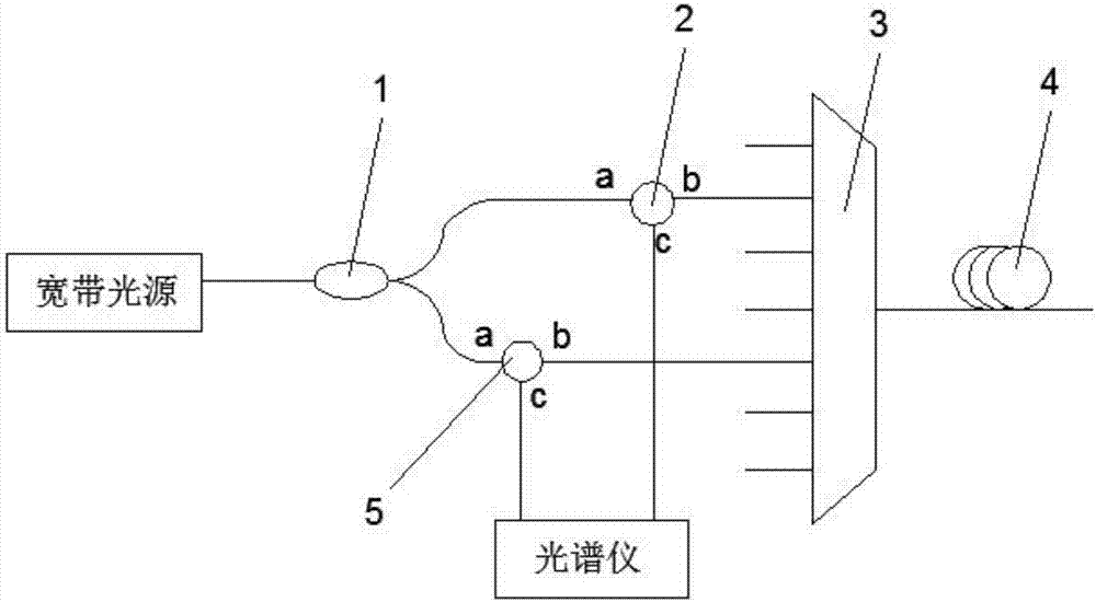
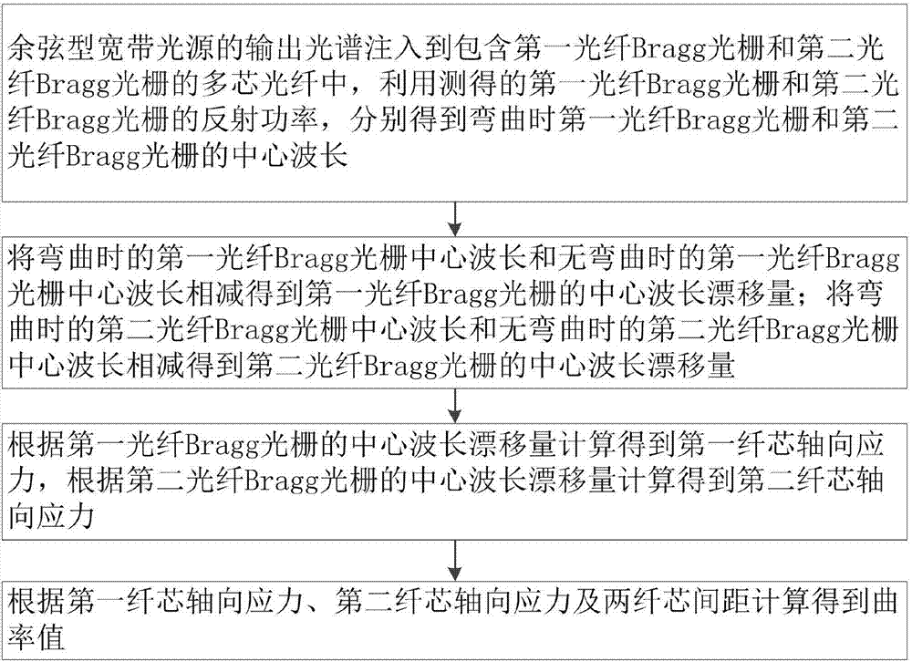
[0017] A demodulation method of multi-core fiber Bragg grating curvature sensor, using cosine-type broadband light source to replace figure 1 In the broadband light source, the optical power meter, photodetector and other instruments that can detect the reflected power are used to replace the spectrometer to realize the demodulation of the central wavelength of the fiber Bragg grating, such as figure 2 shown, including the following steps:

[0018] S1, the output spectrum of the cosine-type broadband light source is injected into the multi-core optical fiber comprising the first fiber Bragg grating and the second fib...


PUM


Abstract

The invention relates to a demodulation method of a multi-core fiber Bragg grating curvature sensor. According to the method, the change of the center wavelength of an optical fiber Bragg grating is converted into the change of the reflection power of the optical fiber Bragg grating by using a cosine type broadband light source; and a corresponding center wavelength is calculated through measuring the reflection power of the optical fiber Bragg grating according to a derived relational expression of the reflection power and center wavelength of the optical fiber Bragg grating, so that the demodulation of the center wavelength of the optical fiber Bragg grating is realized. The multi-core fiber Bragg grating curvature sensor includes two optical fiber Bragg gratings which are respectively located in two fiber cores which are in central symmetry with respective to the section of a multi-core fiber; the change quantity of the center wavelength of the two optical fiber Bragg gratings is obtained according to the FBG center wavelength demodulation method, so that a corresponding curvature value can be obtained. The curvature sensor demodulation technology has the advantages of high sensitivity, simple realization mode, low cost and the like.

Description

technical field [0001] The invention belongs to the technical field of curvature sensor demodulation, and in particular relates to a demodulation method of a multi-core optical fiber Bragg grating curvature sensor. Background technique [0002] Curvature is an important parameter to describe the shape of an object, and the change trend of the shape of the object can be understood by measuring the curvature. Curvature sensors have broad application prospects in structural health monitoring and surface shape measurement. [0003] The curvature sensor based on fiber grating has the advantages of small size, light weight, strong anti-electromagnetic interference ability and quasi-distributed measurement, and is especially suitable for curvature measurement of large structures and harsh environments (M.J.Gander, “Bendmeasurement using Bragg gratings in multi- core fiber," Electronics Letters 36(2), 120-121, 2000.). In recent years, in order to further improve the performance of...

Claims


Application Information

Patent Timeline
Patent Type & Authority Applications(China)
IPC IPC(8): G01D5/353
CPCG01D5/3538
Inventor 郑狄马彦豪潘炜
Owner SOUTHWEST JIAOTONG UNIV
Why Eureka
Try Eureka