
Dynamic magnetic resistance based equivalent reactance transient state modeling method of magnetically controlled shunt reactor
A kind of equivalent reactance, magnetron technology, applied in the direction of instruments, electrical digital data processing, special data processing applications, etc., can solve the problems of magnetic circuit and circuit calculation and analysis obstacles, difficulties, no practical significance, etc.
- Summary
- Abstract
- Description
- Claims
- Application Information
AI Technical Summary
Problems solved by technology
Method used
Image

Examples
Embodiment Construction
[0091] The invention includes the description and simulation modeling method of the iron core structure and working principle of the magnetic control shunt reactor.
[0092] 1MCSR basic magnetic circuit principle
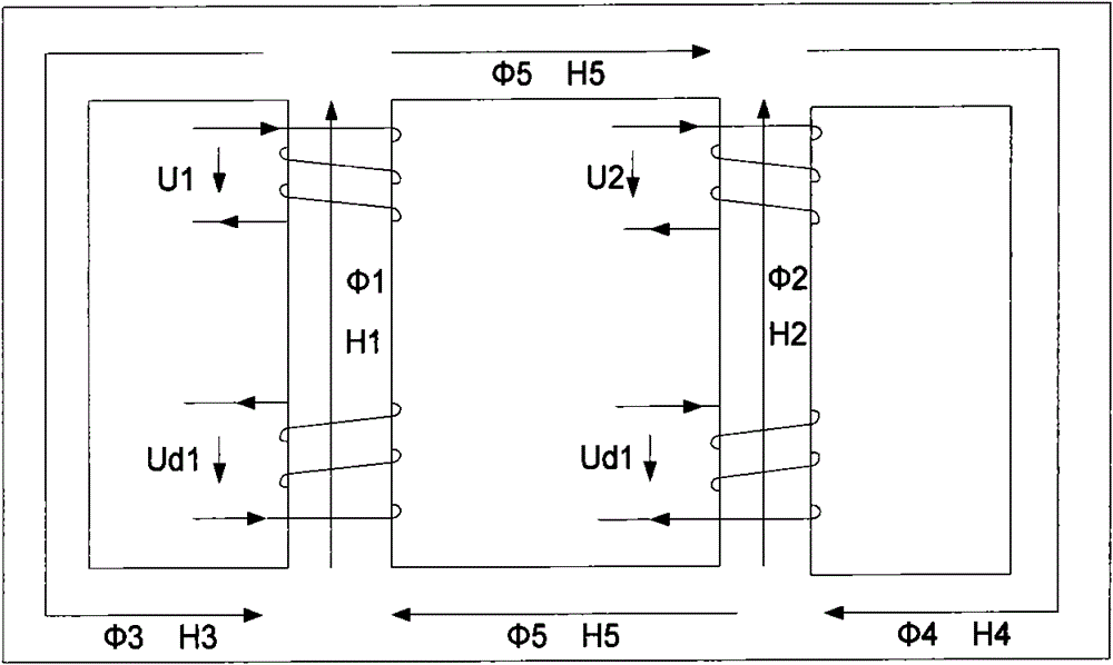
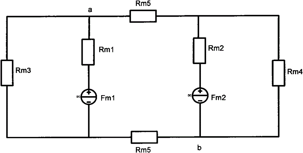
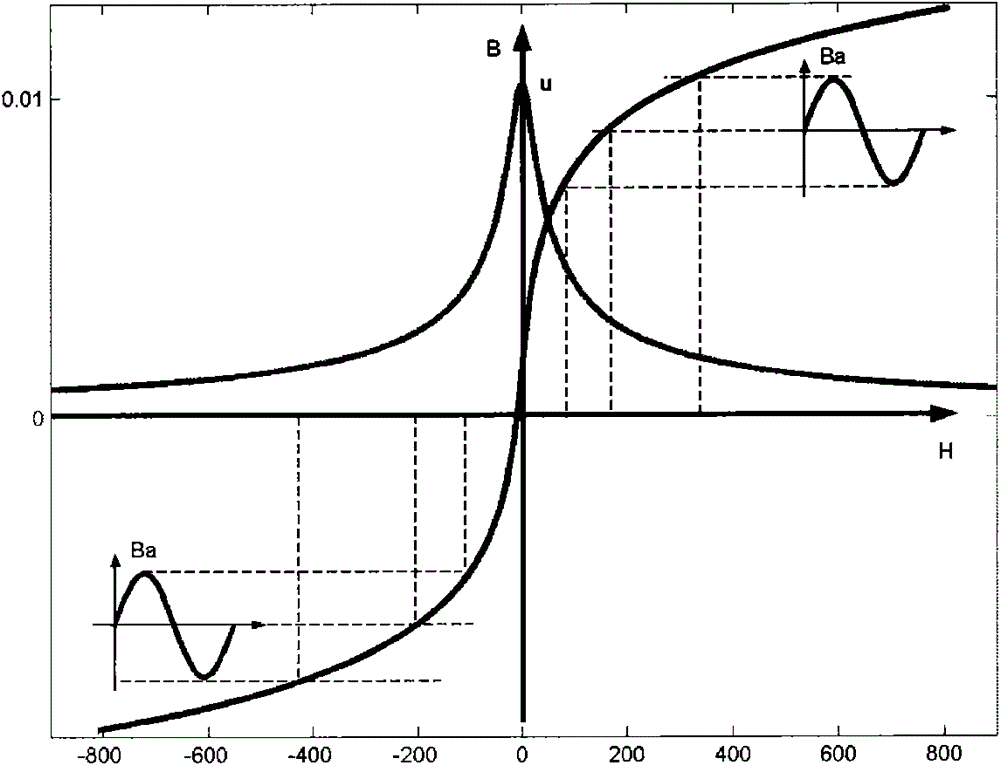
[0093] MCSR uses the characteristics of AC and DC hybrid excitation to change the saturation degree of the iron core, and its winding connection method is as follows: figure 1 As shown, the core of the main magnetic circuit includes two windings, U 1 , U 2 is the AC network side winding, U d1 , U d2 is the DC winding voltage, due to the different permeability of different magnetic circuits, the magnetic flux The reluctance of the two main magnetic circuits where it is located bears the main excitation magnetomotive force in the whole system. The resistance is r, the current is i, H is the magnetic field strength, μ is the magnetic permeability, φ is the initial phase of the AC voltage, S is the equivalent cross-sectional area of the magnetic circuit, and l is ...
PUM
 Abstract
Description
Claims
Application Information