Digital filter design method and device, digital filter design program, and digital filter

A technology of digital filter and design method, applied in digital filter design and device, digital filter design program, digital filter field, can solve problems such as many FIR filters, rounding error, time-consuming, etc. The effect of reducing the number of circuit elements, reducing the circuit scale, and simplifying the structure

Inactive Publication Date: 2007-03-28
NEURO SOLUTION CORP
View PDF1 Cites 3 Cited by
  • Summary
  • Abstract
  • Description
  • Claims
  • Application Information

AI Technical Summary

Problems solved by technology

[0006] However, since the frequency characteristics of the FIR filter obtained by conventional design methods depend on window functions and approximate expressions, unless these are properly set, the desired good frequency characteristics cannot be obtained.
However, in general, it is difficult to properly set the window function or approximation
In addition, when windowing is performed to reduce the number of filter coefficients, the frequency characteristic will produce a truncation error
Therefore, there is a problem that it is very difficult to achieve the desired frequency characteristics with conventional filter design methods.
[0007] In addition, in order to design an FIR filter that achieves the desired frequency characteristics as precisely as possible, the number of filter coefficients reduced by window selection is very limited
Therefore, the number of taps of the designed FIR filter is very large, and the filter coefficient values ​​are very complex and random
Therefore, there is a problem that a large-scale circuit structure (adder, multiplier) is required to realize the number of taps and filter coefficient values.
Therefore, in the past, it took time and effort for skilled engineers to design, and there was a problem that it was not easy to design an FIR filter with desired characteristics.
However, even if any of these methods is used, the passband of the filter can only be narrowed, and it is impossible to precisely realize frequency characteristics of an arbitrary shape with a small number of taps.

Method used


Image

  • Digital filter design method and device, digital filter design program, and digital filter
  • Digital filter design method and device, digital filter design program, and digital filter
  • Digital filter design method and device, digital filter design program, and digital filter

Examples


no. 1 Embodiment approach

[0071] Hereinafter, a first embodiment of the present invention will be described with reference to the drawings. In this embodiment, several kinds of basic filters having specific impulse responses are defined, and by connecting them in cascade arbitrarily, an FIR filter having desired frequency characteristics is realized. Basic filters can be roughly divided into three types: basic low-pass filters, basic high-pass filters, and basic band-pass filters (including comb filters). Hereinafter, these basic filters will be described.

[0072]

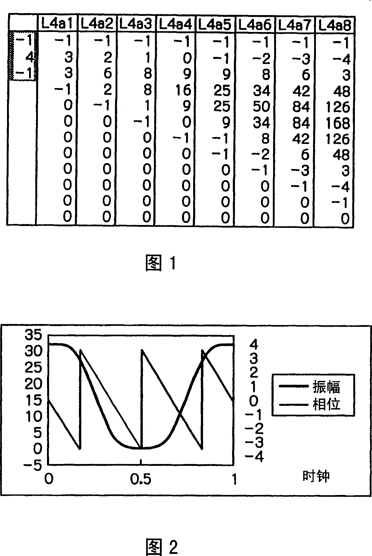
[0073] The filter coefficient of the basic low-pass filter Lman, by starting from the value list of "-1, m, -1", sequentially adds the original data before the operation to the previous data with a specific delay ahead of it. Moving average Obtained by operation.

[0074] FIG. 1 shows filter coefficients of a basic low-pass filter L4an (when m=4). In FIG. 1 , when the j-th filter coefficient from the top of the n-th column is obtained...

no. 2 Embodiment approach

[0210] Next, a second embodiment of the present invention will be described based on the drawings. 37 is a flowchart showing the steps of the digital filter design method of the second embodiment. In addition, FIG. 38 is a frequency characteristic diagram for explaining the concept of the digital filter design method of the second embodiment.

[0211] In FIG. 37, first, the first filter coefficients whose numerical strings are symmetrical are generated (step S1). There is no particular limitation on the method of generating the first filter coefficients. As long as the numerical array of the filter coefficients is symmetrical, a conventional design method using an approximation or a window function can also be used. Alternatively, a plurality of amplitude values ​​representing desired frequency characteristics may be input, the input numerical sequence may be subjected to inverse Fourier transform, and the first filter coefficient may be obtained by windowing the obtained nu...

no. 3 Embodiment approach

[0242] Next, a third embodiment of the present invention will be described with reference to the drawings. 43 and 44 are flowcharts showing the steps of the digital filter design method of the third embodiment. 45 to 48 are frequency characteristic diagrams for explaining the concept of the digital filter design method of the third embodiment.

[0243] 43 is a flowchart showing the flow of overall processing in the digital filter design method of the third embodiment. In FIG. 43, first, a numerical column of filter coefficients is generated as a basic filter of a symmetric type (step S11). The frequency-Zength characteristic of this basic filter has a pass bandwidth of 1 / β (β is an integer equal to or greater than 1) of the sampling frequency fs to be processed by filtering. Fig. 45 shows the frequency-gain characteristics of the basic filter. Fig. 45 shows the frequency-gain characteristics of a basic filter having a frequency bandwidth obtained by dividing half of the sam...


PUM


Abstract

For example, more than one FIR-type basic filters having a symmetric sequence of numbers having a predetermined characteristic as a filter coefficient are combined and connected in longitudinal connection. The filter coefficient is calculated and for the y-bit data of the calculated filter coefficient, the lower bit is cut off for rounding so as to obtain a filter coefficient of x-bit (x < y). Thus, it is possible to significantly reduce an unnecessary filter coefficient without performing the conventional window multiplication. Moreover, it is possible to realize a digital filter having a desired frequency characteristic with a small circuit size and with a high accuracy without causing a truncation error attributed to window multiplication in the frequency characteristic.

Description

technical field [0001] The present invention relates to a design method and device of a digital filter, a program for designing a digital filter, and a digital filter, in particular to a tapped delay formed by a plurality of delayers, and the output signals of each tap are respectively digitalized. The FIR filter and its design method are the type of FIR filter and its design method that are output by adding their multiplication results after being multiplied. Background technique [0002] In various electronic machines provided in various technical fields, some kind of digital signal processing is usually carried out inside them. Among the most important basic operations of digital signal processing, there is filtering processing to extract only signals in a necessary frequency band from an input signal mixed with various signals or noise. Therefore, digital filters are often used in electronic equipment that performs digital signal processing. [0003] Most digital filte...

Claims


Application Information

Patent Timeline
Patent Type & Authority Applications(China)
IPC IPC(8): H03H17/06
CPCH03H17/06H03H2017/0072G06F17/10G06F30/00
Inventor 小柳裕喜生
Owner NEURO SOLUTION CORP
Why Eureka
Try Eureka