Energy recovery from waste heat sources

a waste heat source and energy recovery technology, applied in steam engine plants, machines/engines, mechanical equipment, etc., can solve the problems of high noise and inefficiency of large “off-road” diesel engines, hazardous combustion conditions, toxic, acidic, noise pollution, etc., to reduce emissions, resist acidic corrosion, and maximize thermal energy recovery

Inactive Publication Date: 2008-12-30
KNAPTON BRENT WILLIAM +1
View PDF9 Cites 56 Cited by
  • Summary
  • Abstract
  • Description
  • Claims
  • Application Information

AI Technical Summary

Benefits of technology

[0009]In some embodiments, three integrated phases may be used to reduce emissions, recover and convert thermal energy into power, and cool inlet combustion air. In some embodiments, the first phase may be emissions reduction that targets nitrous oxide compounds (NOx), carbon monoxide (CO), uncombusted hydrocarbons (CH4) and large diameter particulate matter (PM). When integrated with the second thermal recovery and conversion phase, more pollutants may be removed such as volatile organic compounds (VOC's), acids such as sulfuric acid (H2SO4), and additional particulate matter (PM). In some embodiments, an ammonia injection system may be designed to eliminate extraneous equipment and hazardous re-circulation lines by directly vaporizing, injecting, and mixing the ammonia using a specially designed nozzle.
[0010]In various embodiments, after emissions have been reduced, the second phase may utilize a modified organic Rankine cycle and provide energy recovery from diesel engine(s) exhaust (5-50 MW range) and auxiliary systems and may convert the recovered energy into usable power. While embodiments are described for a diesel engine, the systems and methods described herein may also be used for other waste heat sources including gas turbines, flue stacks, geothermal sources, etc. In some embodiments, a preheat / vaporizer / superheater device may be used to convert ammonia liquid into a superheated vapor that is then passed through a turbo-expander loaded with a generator to produce electricity. In some embodiments, the system may be designed to operate on a smaller scale and, in order to maximize the thermal energy recovery, the outlet temperature of the exhaust may be brought just below acid dew points. The metallurgy in the equipment may be designed to resist acidic corrosion and reduce the amount of acid that escapes into the atmosphere.
[0011]In various embodiments, the third phase may include inlet combustion air chilling. Chilled water from an adsorption process may be used to cool hot ambient combustion air approximately more than 40% to increase diesel engine efficiency and thereby reduce fuel demand and consequently operating costs while improving performance.

Problems solved by technology

Large “off-road” diesel engines may be notoriously loud and inefficient.
The hot exhaust contributes to thermal, toxic, acidic, and noise pollution.
Other systems may re-circulate a hot exhaust slip stream directly into the ammonia system to provide a direct source of vaporization, however, this may create a hazardous combustion condition depending upon the concentration of ammonia being injected.
Unfortunately high concentrations of acidic vapor are released into the atmosphere where eventual cooling and condensation leads to acid rain, a human health hazard and destructive property problem as well.

Method used


Image

  • Energy recovery from waste heat sources
  • Energy recovery from waste heat sources
  • Energy recovery from waste heat sources

Examples


Embodiment Construction

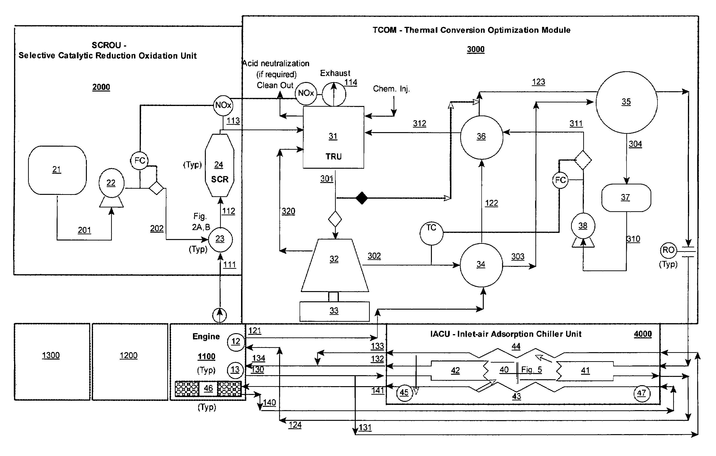
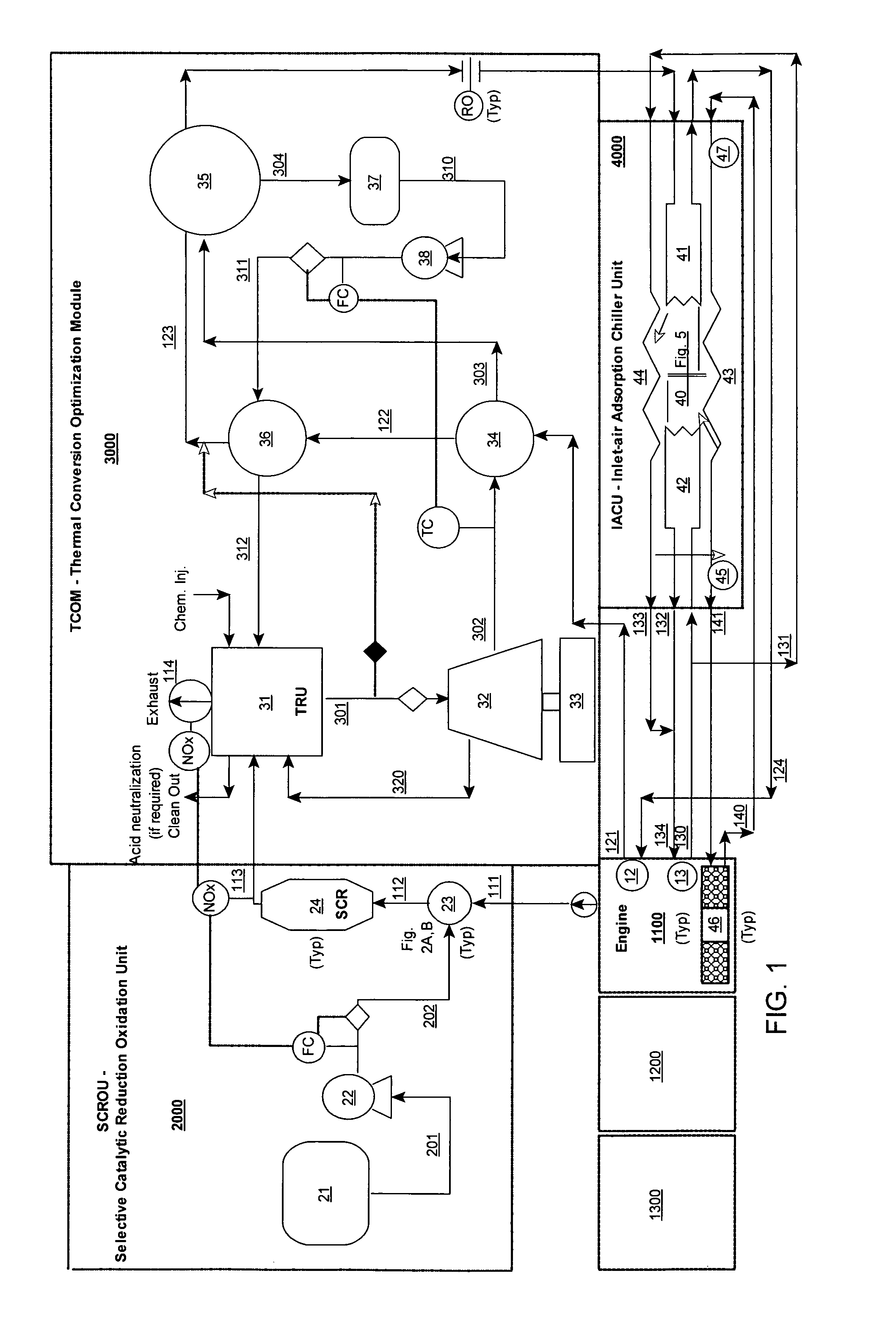
[0027]FIG. 1 illustrates a process flow diagram of a stationary diesel engine(s) equipped with emissions reduction 2000, thermal recovery and conversion 3000, and inlet air chiller 4000 units, according to an embodiment. In some embodiments, three integrated phases may be used to reduce emissions, recover and convert thermal energy, and cool inlet combustion air to improve overall diesel engine efficiency and performance. While embodiments described herein identify a diesel engine, it is to be understood that the following embodiments may be used with other types of engines.

[0028]In some embodiments, a reciprocating engine(s) 1100 may be coupled to a Selective Catalytic Reduction Oxidation Unit SCROU 2000 including, in part, a Selective Catalytic Reactor SCR 24 which may act as a partial particulate matter (PM) filter and noise silencer. As used herein and on the FIGs, “(Typ)” stands for typical to indicate more than one expected use in the Figures (i.e., at least parts with a “(Typ...


PUM


Abstract

In some embodiments, three integrated phases may be used to reduce emissions, convert thermal energy into electricity, and cool inlet combustion air. An ammonia injection system may be designed to eliminate extraneous equipment and hazardous re-circulation lines by directly vaporizing, injecting, and mixing ammonia using a specially designed nozzle. The second phase may include using a preheat / vaporizer / superheater exchanger to convert ammonia liquid into a superheated vapor that is then passed through a turbo-expander / generator to produce power. In some embodiments, the third phase may include inlet combustion air chilling.

Description

PRIORITY CLAIM[0001]This application claims benefit of priority of U.S. Provisional Patent Application Ser. No. 60 / 605,813 titled “Energy Recovery From Waste Heat Sources”, which was filed Aug. 31, 2004, whose inventors are Brent William Knapton and Craig A. Beam which is hereby incorporated by reference in its entirety as though fully and completely set forth herein.BACKGROUND OF THE INVENTION[0002]1. Field of the Invention[0003]The present invention relates generally to engines / turbines and, more specifically, to engine / turbine energy recovery.[0004]2. Description of the Related Art[0005]Large “off-road” diesel engines may be notoriously loud and inefficient. They may convert approximately 40% of available energy in the form of combusted fuel into effective work (or electric power if a generator set is coupled to the engine). Approximately 60% of the energy produced may be waste heat that is either rejected indirectly to the atmosphere via cooling water / air systems or directly rel...

Claims


Application Information

Patent Timeline
Patent Type & Authority Patents(United States)
IPC IPC(8): F01K23/10
CPCF01K25/106F01N3/2066F01N5/02F01N2610/10Y02T10/16Y02T10/24Y02T10/12
Inventor KNAPTON, BRENT WILLIAMBEAM, CRAIG A.
Owner KNAPTON BRENT WILLIAM
Why Eureka
Try Eureka