Precision measuring gauges with optical fiber output channels

a technology of optical fiber and output channel, applied in the direction of photometry using electric radiation detectors, optical radiation measurement, instruments, etc., can solve the problems of limited use of electronic gauges, as opposed to all-optical gauges, and achieve high accuracy, high speed configuration, and economic

Active Publication Date: 2005-10-13
MITUTOYO CORP
View PDF13 Cites 55 Cited by
  • Summary
  • Abstract
  • Description
  • Claims
  • Application Information

AI Technical Summary

Benefits of technology

[0011] In accordance with a separate aspect of the invention, the fiber-optic detector channels are arranged in balanced pairs, to provide enhanced accuracy.
[0012] In accordance with a further aspect of the invention, three or more balanced pairs of fiber-optic detector channels are signal processed in a manner that provides enhanced accuracy.
[0013] In accordance with a separate aspect of the invention, the light source is provided by an optical fiber, to provide an all-optical precision measuring gauge, free of all limitations and costs associated with electronic assembly and electronic signals.
[0017] In accordance with a separate aspect of the invention, a periodic light pattern that moves in correspondence to the scale grating is an interferometric light pattern, and the fiber-optic readhead that detects the location of the scale grating is a high-resolution interferometric-type fiber-optic readhead similar or identical to one disclosed in U.S. patent application Ser. No. 10 / 674,619 to Tobiason, which is incorporated herein by reference in its entirety, and which is hereinafter referred to as the '619 Application. Such an interferometric-type fiber-optic readhead provides a gauge that has certain advantages over previously known gauges that have reasonably compact dimensions. For example, compared to known crude fiber-optic gauges and gauges that include “shadow” type, or self-imaging type readheads, this interferometric-type readhead can operate with a relatively smaller scale pitch, in order to conveniently provide finer measurement resolution. Furthermore, such an interferometric-type readhead can operate reliably over a much larger range of operating gaps relative to the scale grating, allowing simpler and more economical gauge fabrications and assembly and more reliable operation.
[0024] In accordance with another aspect of the invention, the gauge is any measurement gauge that is usable in an application where a gauge having a fiber-optic cable may be used. In accordance with another aspect of the invention, in various embodiments, the gauge provides a measuring resolution less than or equal to at least one of 50, 20 or 10 nanometers. In accordance with another aspect of the invention, in various embodiments, the gauge provides high resolution and high accuracy measurements, while providing at least one outside dimension that is less than or equal to at least one of 20, 15, 10 or 7 millimeters. In accordance with a further aspect of the invention, in various embodiments, the gauge includes an interferometric-type fiber-optic readhead.
[0035] Hence, the invention overcomes the disadvantages of prior art precision measuring gauges and provides new application possibilities with an ultra-compact, highly accurate, economical, and high speed configuration.

Problems solved by technology

Electronic gauges, as opposed to all-optical gauges, suffer limitations in converting the high frequency detector signals associated with high speed scale motion and transmitting those signals over long cables without significant signal loss or interference.

Method used


Image

  • Precision measuring gauges with optical fiber output channels
  • Precision measuring gauges with optical fiber output channels
  • Precision measuring gauges with optical fiber output channels

Examples


Embodiment Construction

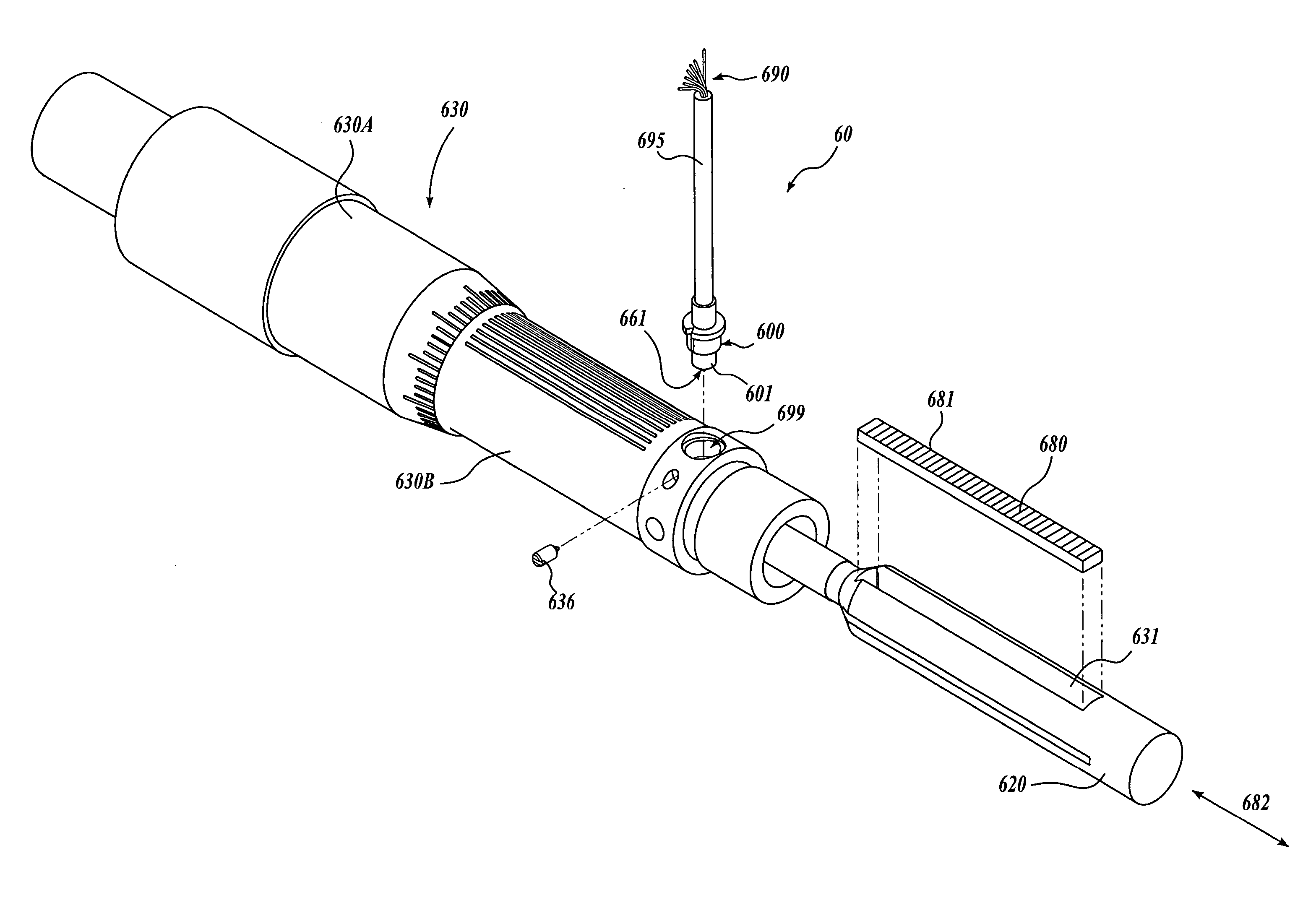
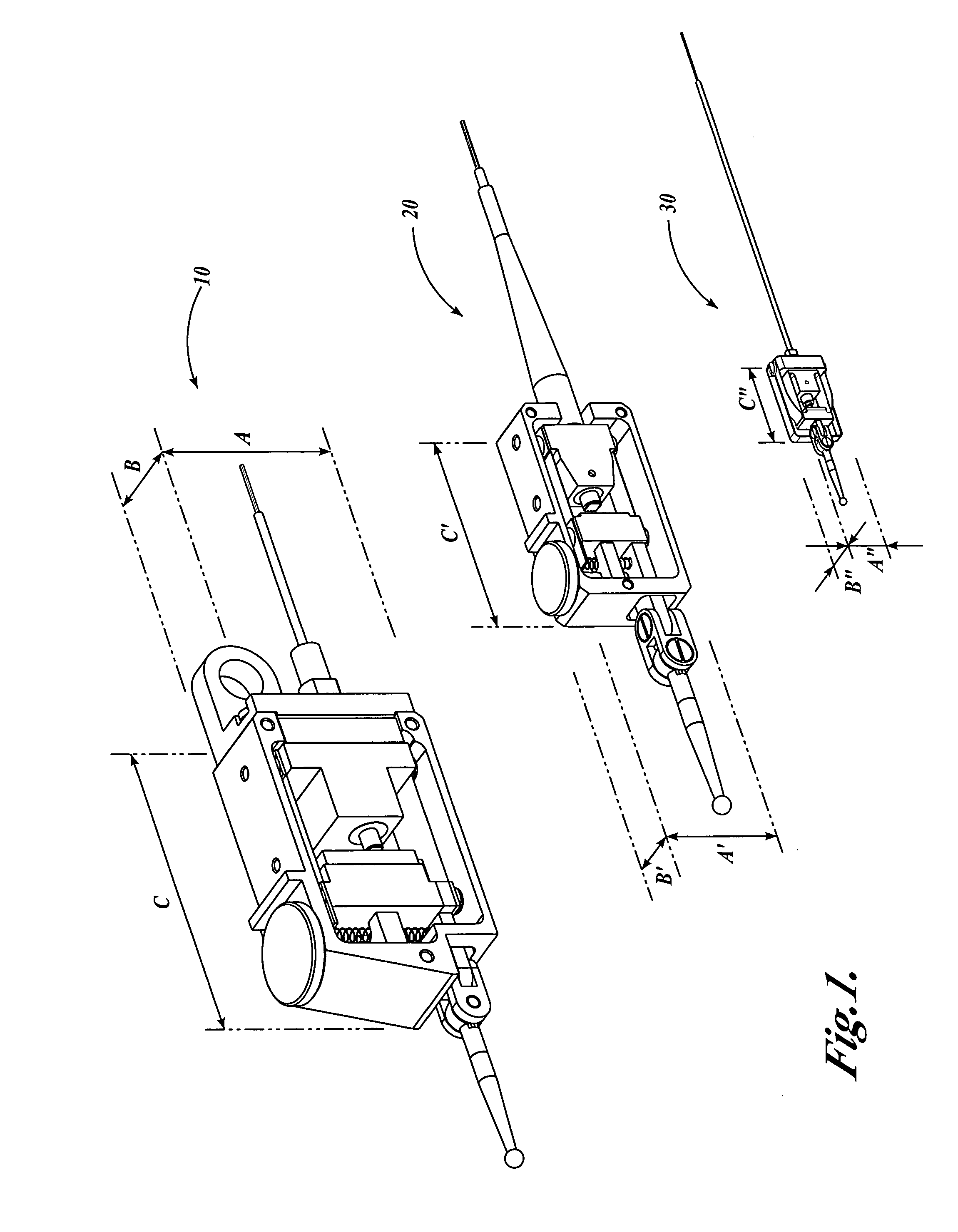
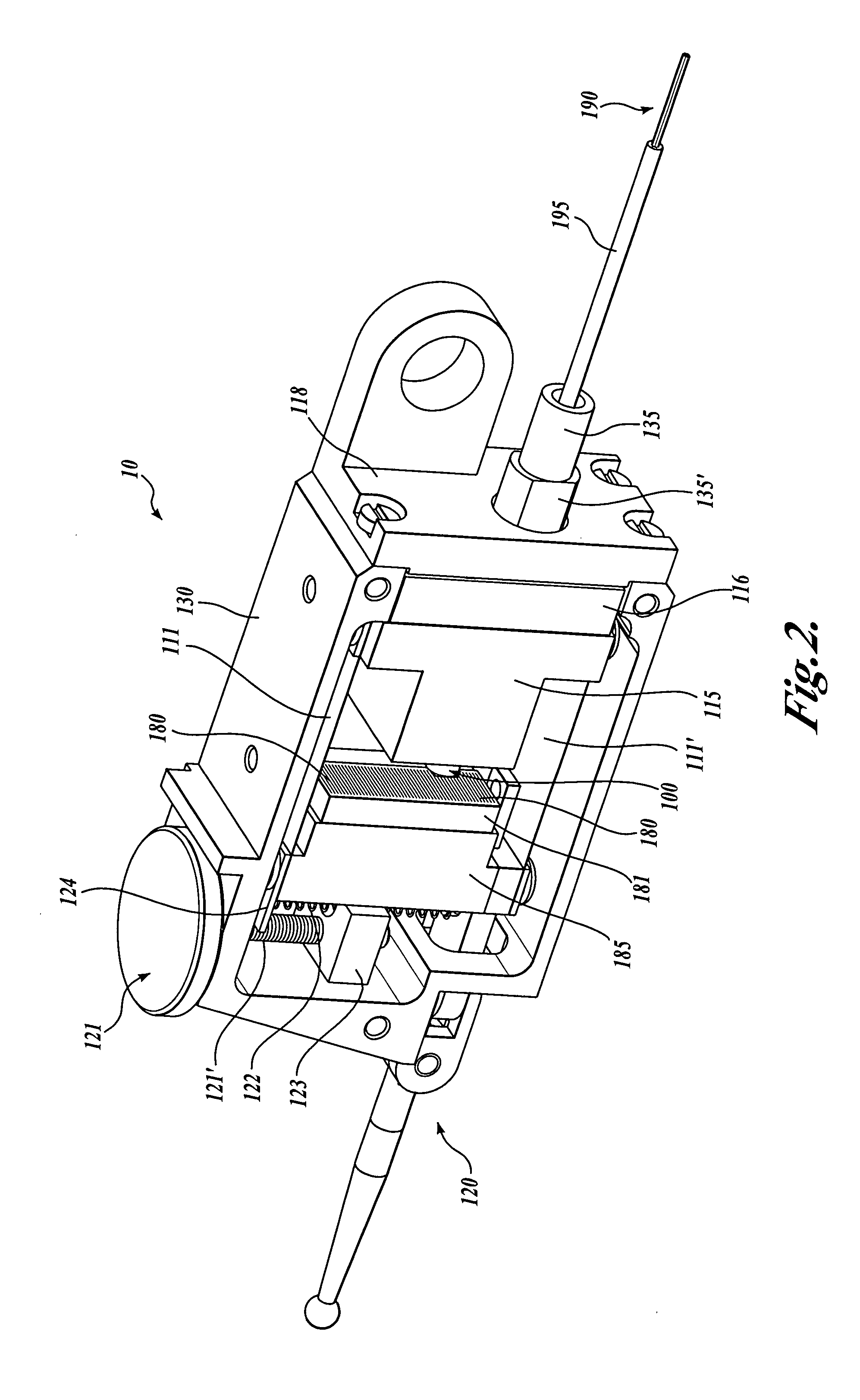
[0056]FIG. 1 is an isometric view showing a first larger-sized generic embodiment of a fiber-optic lever gauge 10 according to this invention, a second medium-sized generic embodiment of a fiber-optic lever gauge 20 according to this invention, and a third smaller-sized generic embodiment of a fiber-optic lever gauge 30 according to this invention. Analogous elements numbered 1XX, 2XX, and 3XX in FIGS. 1-8 provide similar or identical functions, unless otherwise indicated by description or context. Therefore, only the differences between similarly numbered elements are described after any initial description of one of the similarly numbered elements. The fiber-optic lever gauges 10, 20 and 30 are shown approximately very roughly to scale relative to each other in FIG. 1, to emphasize with regard to the fiber-optic lever gauge 10 that a fiber-optic lever gauge according to this invention can be constructed in a conventional size; and with regard to the fiber-optic lever gauge 20 that...


PUM


Abstract

All-optical output precision measuring gauges that sense the displacement of an internal scale grating are disclosed. Each type of gauge includes a compact, miniature, or ultra-miniature optical readhead that includes a light source for transmitting light to the scale grating, and optical-fiber detector channels for receiving light from the scale grating and outputting optical measuring signals from the gauge. In various embodiments, the optical-fiber detector channels have respective phase grating masks for receiving a periodic light pattern that moves in correspondence to the scale grating, and the channels are arranged in balanced pairs. In various embodiments, the optical readhead is an interferometric-type optical readhead that provides a measuring resolution as fine as 10-50 nanometers or less. In various embodiments, the gauge is provided in an unprecedented miniature size. In various embodiments, the gauge is motorized to provide a precision actuator.

Description

CROSS-REFERENCE TO RELATED APPLICATION [0001] This application claims the benefit of U.S. Provisional Application No. 60 / 560,995, filed Apr. 9, 2004FIELD OF THE INVENTION [0002] This invention relates generally to precision measuring gauges and actuators, and particularly to contact-type precision measuring gauges and actuators that use internal grating scales and optical displacement measuring systems for determining the grating scale displacement. More particularly, this invention relates to an all-optical measuring system for such gauges, using optical fibers as receiver and output channels to provide an ultra-compact high accuracy system. BACKGROUND OF THE INVENTION [0003] Various precision measuring gauges for sensing linear, rotary or angular displacement or dimensions are currently available. These gauges are generally based on either optical systems, magnetic scales, inductive transducers, or capacitive transducers. [0004] For gauges based on optical systems, a number of dif...

Claims


Application Information

Patent Timeline
Patent Type & Authority Applications(United States)
IPC IPC(8): G01D5/34G01D5/353G01J1/04G01J5/08G02B6/38
CPCG01D5/35303G02B6/381
Inventor TOBIASON, JOSEPH D.ZWILLING, AVRONEMTMAN, CASEYHARSILA, SCOTTGOLDSWORTHY, MIKEATHERTON, KIM W.
Owner MITUTOYO CORP
Why Eureka
Try Eureka